Ranking Electrical Disturbances ― Part 7 of 7
This article is the final installment in a seven-part series on the effects of power quality disturbances on a five-stage electronic LED driver. In the first three parts of this series, we touched upon the effects of short- and long-duration voltage variations (under-voltage, over-voltage and voltage sags) on LED drivers. Then, we looked at the effects of voltage surges, swells, and transients on LED drivers. Parts 4 through 6 of the series dealt with the immunity of imbalances, frequency shifts, and harmonic distortion on drivers. We learned that these disturbances — some destructive to driver electronics like surges and transients and most non-destructive like sags, imbalances, frequency shifts and harmonics — can impact the life of driver electronics. In most cases, the LED light is only affected if the DC bus level decreases or increases. However, in the case of voltage fluctuations (or flicker), steady-state perturbations in the AC line voltage can cause the DC bus to fluctuate in a steady fashion as well if the power electronics and passive networks can’t filter these perturbations. This last article addresses one of the most important power quality (PQ) topics for electronic lighting systems — immunity to voltage fluctuations.
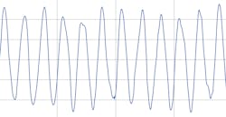
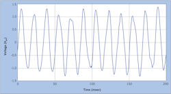
Figure 1 illustrates an example of a PQ recording from a 480V bus in a steel mill. Here, the voltage is scaled to a 1.0 per unit (p.u.) normalization, where 1.0 is equivalent to 480V. You can see that the peak voltage is most often affected. The shape of the maxima and minima, as well as the positive and negative slopes of the sinewave, are affected too, but not nearly as much as the peaks. Sometimes, the peaks contain significant distortion. However, you should also note the changing peaks seem to fit an “envelope” in the positive and negative parts of the sinewave to form a “boundary.” In fluctuating voltages, this envelope is typically consistent with respect to time and represents the fluctuating (or flicker) frequency. It typically ranges from 2 Hz to 25 Hz.
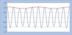
The fluctuating peaks are also typically non-destructive to driver electronics even though the peaks can reach levels as high as 1.5 p.u. This level is short-lived within less than a half cycle of the voltage. If such levels were steady state, as in the case of a voltage swell, the driver electronics on the front end would be damaged. In Fig. 2, you can see that voltage fluctuations affect amplitude (the peaks are constantly changing), frequency (a new low frequency called flicker frequency is added), and wave shape (the peaks and positive and negative slopes of the changing voltage is typically not a pure sinewave).
Causes and Sources of Flicker
Fluctuating voltages are caused by rapid changes in load or current. If the load changes rapidly from cycle to cycle — and the power system cannot maintain a constant voltage within that change — the voltage will fluctuate. One limiting factor is the short-circuit current capacity (SCCC) of the system upstream of the fluctuating load. Voltage sources with a lower SCCC have a higher propensity to cause flicker. Typical causes and sources are found in industrial customer settings in industrial plants.
The most common cause of flickering voltage is the electric arc furnace (EAF) found in steel and other metal-producing facilities. The starting of large motors is another typical cause. The operation of large variable-frequency drives (VFDs), frequency converters, and cyclo-converters are other causes. Devices that change the inductive component of voltage sources are also causes of flicker. These include switching capacitors, tap-changing transformers, and step voltage regulators. Regarding wiring problems, low-current loose connections can be causes of long-duration flicker as well as opposed to those with higher current, which can be found with thermal scanning and inspection of burned conductors.
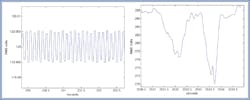
Figure 3 shows how a 120V (left) and 277V (right) branch circuit in a facility can be impacted by a high-power source of voltage flicker. Notice in the 120V plot on the left that the AC voltage level fluctuates significantly and is consistent with a definable flicker frequency. The plot on the right is the voltage on a 277V branch circuit in the same industrial facility. This voltage trend has a more random profile. Both voltage sources impacted by this flicker source will have a noticeable impact on the luminous performance of LED lighting devices. In fact, it has been shown in other previous investigations that much lower flicker levels will cause noticeable effects in today’s LED luminaires.
LED driver designers and fixture manufacturers can expect to see increases in the number of LED luminaires used in commercial and industrial customer environments, as well as the number of high-power fluctuating loads. Customers are installing higher power VFDs where they were never used before. Customers are also replacing older VFD technologies with newer ones that feature advanced modulation schemes. This will cause the flicker levels and frequencies in these facilities to increase beyond the levels we’ve seen over the last decade.
Effects on Incandescent Lamps
Incandescent lamps respond to fluctuating voltages by exhibiting a flicker in the light produced by the lamp. IEEE Standard 141 – 1993, Recommended Practice for Electric Power Systems, defined the first flicker curve for an incandescent lamp. This curve defines the borderline of visibility of flicker (lower curve) and the borderline of irritation (upper curve) as a function of time [30 min. (left) to 0.05 sec (right)] between fluctuating voltages and percent (0% to 6%) of fluctuating voltage. This curve has been widely used to study flicker and the human eye’s response to flickering light sources, including those for electronic lighting systems.
Although significant advancements (see IEEE and IEC standards on flicker) have been made in how flicker is measured, no standards have been developed for limiting the flicker immunity of electronic light sources to fluctuating voltages caused by fluctuating loads. Now that the market penetration of LED light sources is growing significantly in all customer sectors (residential, commercial, and industrial), flicker limits for LED lighting should be studied carefully.
LED Driver Design and Flicker
Designers of traditional electronic light sources designed their electronics around lamp responses for known fluorescent and high-intensity discharge (HID) lamps, including compact fluorescent lamps. The availability of advanced electronic digital components was limited during the early days of this technology. However, as LED technology advanced, designers began to learn how to increase the immunity of LED drivers to fluctuations. Typical voltage fluctuation waveforms from the field combined with a repeatable flicker generating and measurement capability are now two tools that make this endeavor possible. Moreover, the availability of advanced digital controls for LEDs and their arrays provides a path for developing well understood flicker immunity performance criteria for many of today’s LED light sources.
Figure 4 shows the simplified block diagram for an LED driver with five stages. Notice in the figure that a short-lived fluctuating voltage source will produce a perturbed light level. Well-understood design and performance criteria for power factor correction (PFC) stages is another very valuable tool for studying flicker performance and immunity for LED drivers. The filtering and control of the DC bus when voltage flicker is present on the AC bus will be needed as well as the smoothing and shaping of the DC voltage and current delivered to the LEDs and arrays. This will help manufacturers and test engineers understand how to determine consistent flicker performance criteria, thus leading to flicker limits for LED light sources.
Keebler is a power systems and power quality engineer and can be reached at [email protected].
About the Author
Philip Keebler
Senior Power Quality Engineer
Philip F. Keebler, MSEE has 32 years of experience in power quality (PQ) having worked for North American Philips, Electric Power Research Institute (EPRI), Electrotek Concepts & Dranetz. His experience spans across the utility revenue meter addressing PQ problems on the grid and inside residential, commercial and industrial customer facilities. His specialty areas include grounding, disturbances, harmonics, electromagnetic interference (EMI), equipment immunity, PQ monitoring, training and standards development. He serves as a Technical Advisor to PBE Engineers, LLC focused on understanding, identifying, solving and preventing (UISP) PQ problems in the industry and fostering new interest and workforce development to attract young engineers to developing careers in PQ. He can be reached at [email protected].


