The Basics of Vector Analysis Part 2
The Basics of Vector Analysis Part 1
The Basics of Vector Analysis Part 3
The Basics of Vector Analysis Part 4
Last month, we clarified the definition of a vector and showed you how vectors are added, subtracted, multiplied, and divided. This month, we'll see how to use vectors in defining a complex circuit with resistance and inductive reactance to determine the total current of that circuit.
Some electrical devices, such as motors, present a combination of resistance and inductance to current flow through them. Other devices, such as resistance heaters, are almost all resistance. In many cases, it's common to find a pure resistance load in parallel with another load made up of resistance and inductance in series. Or, a capacitance might be connected in parallel with a load made up of resistance and inductance in series. Called ¡°complex circuits,¡± these circuits are actually combinations of series and parallel circuits.
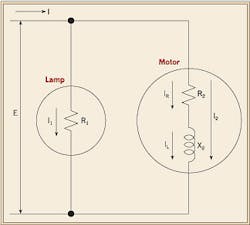
A basic complex circuit would be a 120V branch circuit supplying an incandescent lamp and a motor, with the loads connected in parallel. The lamp load is pure resistance while the motor load is actually a series connection of the resistance and inductance of the motor coil windings. Figure 1 shows a schematic of this circuit.
Current flow through resistance, inductance
In AC circuits, the waveform character of current, relative to voltage, is very important. Depending on the type of load, differing phase relationships will exist between current and load voltage.
When AC voltage is applied to a circuit containing resistance only, the resulting current waveform is produced by the voltage waveform. In such a circuit, the current and voltage waves pass through their zero values and increase to their maximum values in the same direction and at the same time. They are said to be ¡°in phase.¡± This is because the current encounters no opposing electromotive force (EMF).
However, in circuits that contain opposition to current flow other than resistance, such as magnetic coils and motors, the current and voltage waves do not go through their zero and maximum values at the same time. Instead, there is a fixed time interval between their respective zero and maximum values. In this case, the current is said to be ¡°out of phase¡± with the voltage. This is also true for current flow through an inductance because a magnetic field is set up around the coil, inducing an opposite EMF in it and causing the circuit current to lag behind the circuit impressed voltage.
Now, depending on the particular conditions of a circuit, a current may lead or lag the voltage by any value up to ¨ù cycle, or 90¡Æ. We commonly express this phase difference in electrical degrees and call it the ¡°phase angle¡± of the circuit. We also commonly use the Greek letter theta (¥È) to designate it.
Let's see how this angle enters into the vector analysis of a complex circuit later on in the article.
Vector analysis of lamp circuit
Referring back to our basic complex circuit, as shown in Fig. 1, let's begin the vector analysis by constructing a vector diagram for each load. Remember that we're using boldface type to designate vectors.
Looking at Fig. 1, we can see that the incandescent lamp portion of the circuit has current I1 flowing through resistance R1. As previously stated, this current is in phase with the circuit voltage (E). In other words, phase angle ¥È is equal to zero. So, the current vector I1 and voltage vector E are somewhat superimposed on each other, with the magnitude of E being larger than that of I1 (Fig. 2 on page C12).
Vector analysis of motor
In the motor portion of the complex circuit shown in Fig. 1, current IR flowing through resistance R2 is in phase with the circuit voltage. Therefore, vector IR will be superimposed on vector E. As is the case with current flowing through an inductance, the current IL will be 90¡Æ out of phase with the voltage. Therefore, vector IL will be 90¡Æ from IR. By adding IL and IR, we get vector I2, which is the total current flowing through the motor.
Note that this current lags the circuit voltage by angle ¥È1, so the angle between I2 and IR is also ¥È1 (Fig. 3).
Vector analysis of complex circuit
By referring back to Part 1 in the August 2008 issue and using the parallelogram method to add the resulting vectors of Fig. 2 and Fig. 3, the result, as shown in Fig. 4, is the vector diagram of our basic complex circuit. Here, vector I, which represents the total current of our complex circuit, is the resultant of vectors I2 and I1. This current will lag the voltage E by an angle ¥È2, which is the angle between I and E.
Next month in Part 3, we'll see how you can use vector analysis to calculate neutral currents in 3-phase, 4-wire circuits.
