For 30-plus years, I have helped electrical contractors install busway systems. Typically, I don’t get involved until after the busway is completely installed and a problem is discovered while performing an insulation resistance test of the complete system — or when there’s a failure. In my experience, the most common and costly mistake electrical professionals make when installing busway is the failure to evaluate each busway section as it is installed.
Establishing a proper testing protocol
When doing this type of work, all testing is performed on de-energized equipment using personal protective equipment (PPE) following NFPA 70E and facility-required safety practices. For a list of busway system installation and testing best practices, read the sidebar below.
A total of 10 measurements should be taken on 3-phase, 4-wire systems after each component is connected — three phase-to-phase, three phase-to-neutral, three phase-to-ground, and one neutral-to-ground test. A 3-phase, 3-wire system requires six measurements to ensure system integrity — three phase-to-phase and three phase-to-ground tests.
A good practice is to perform an insulation resistance test on each component individually before installation and after each busway component is connected. Tests should be conducted in a temperature and humidity-controlled environment. Apply 1,000V for a minimum of 30 seconds, and record the readings. Any substantial difference in readings could indicate a problem. A good reason to evaluate it before installation is that you can identify a defective component before it’s installed say 30 feet above the floor.
Technical testing troubleshooting tips
An all-important — and an often overlooked measurement in a 3-phase, 4-wire application — is the neutral-to-ground test. If the neutral is unintentionally connected to ground in a busway, a prohibited neutral-to-ground bond is created. As a result, current could flow on the grounded parts and equipment resulting in a shock hazard. Any neutral-to-ground connection in a 3-phase, 4-wire system other than the neutral-to-ground bond in the switchboard can cause protective device equipment failures resulting in fire and /or nuisance tripping. In addition, system noise, surges, ground loops, overall poor power quality, and improper operation of sensitive equipment can result from prohibited neutral-to-ground bonds.
As part of equipment start-up, evaluating the busway insulation reading may indicate there is an improper neutral-to-ground connection present in an installation. The first step to locating this is to isolate the busway from the switchboard and other components/ equipment. Once a short is discovered, the most common procedure employed to find the fault is to remove a joint pack near a mid-run point and perform insulation resistance testing in both directions. Continue to remove joint packs at other halfway points on the remaining busway sections, and you’ll eventually locate the problem.
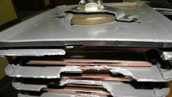
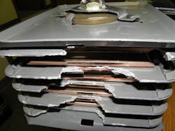
As indicated, this is the most widespread test practice, but it can be costly and dangerous. Trying to remove a joint pack 30 feet above the floor is possible but typically results in irreparable damage to the joint packs (Photo 1). And if it’s hard to remove, it will be even harder to replace. I have seen this procedure create new shorts during the removal/replacement process. The fewer you must remove, the better.
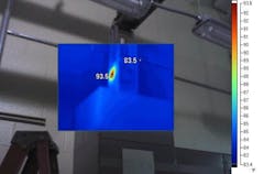
A safer and overall less expensive test procedure is to use a high current test set and inject current into the busway at one end, typically at the switchboard location. Inject current at approximately 25% of the busway rating (e.g., 200A for a 800A busway) and use an infrared camera to scan the entire run. After a set amount of time (based on the length of the run from the switchboard), the joint pack where the busway is shorted will show an increase in temperature. If the fault is between joint packs, which is rare, only the sections between the fault and the current source will show an increase in temperature (Photo 2). The point where the transition occurs (warm to cold) is the location of the short. At worst, you must remove and re-install one joint pack. This procedure will work to locate multiple shorts. The shorts must be corrected one at a time. This procedure will work to locate a short in an old busway run.
If the run is long, begin by conducting a test at each end. Adjust the output rheostat to get the desired current. The closer you are to the short, the less you’ll have to increase the output. Then, inject current on the end closest to the short, and wait for it to heat up. As an example, a test on the first floor of a building required increasing the output rheostat less than half of what was required on the 11th floor. The short was found in a joint pack at the motor control center (Photo 3).
Considering the weight of one section of busway — and having to address an issue 30 feet above the floor — an ounce of prevention is truly worth a pound of cure. It is highly recommended to test each individual section as it’s installed. The measured readings will be affected by temperature and humidity, so proper storage prior to installation is necessary. Once the installation is complete, compare the final readings to the manufacturer’s recommendations based on the total length of the run. For example, meg-ohms = 100 / length of the run in feet or meg-ohms = 30.5 / length of the run in meters. The meg-ohm readings should not be less than the value calculated from the manufacturer’s formula. If readings are less than the calculated value, contact the manufacturer.
Insulation resistance readings are impacted by temperature and humidity. When the busway is installed in an open unheated building, it may be necessary to conduct the final readings after the building is enclosed and the temperature and humidity has stabilized.
Busway System Best Practices
- Store busway indoors in a dry, clean location.
- Inspect for shipping damage.
- Test each section prior to installation.
- Test busway after each component is installed including bus plugs on feeder busway systems.
- To prevent a shock hazard and ensure the proper operation of protective devices, verify there are no neutral-to-ground connections in 3-phase, 4-wire busway systems. The only connection allowed is the neutral to ground bond in the main switchboard, as per NEC Art. 250.
- Compare the calculated values based on the manufacturer’s formula to the measured values. Record these readings.
- Energize the breaker or switch feeding the busway first, followed by feeder devices and then branch circuit devices. Do not energize with loads applied.
- Perform an infrared inspection at all connections and joint packs after load is applied to ensure good connections. As part of a preventive maintenance program, an annual inspection of busway systems should include an infrared evaluation.
- Never attempt any measurements on an energized busway. Infrared allows you to safely evaluate busway from a distance.
- Only qualified electrical maintenance personnel should install and/or maintain busway systems.
About the Author

Bennie Kennedy
Licensed electrical contractor Bennie Kennedy is a nationally recognized authority on electrical systems/safety with more than 40 years of experience in the electrical industry. He has trained and spoken to hundreds of organizations nationally and authored numerous published articles on low- and medium-voltage power distribution systems and safety. He has been authorized by the U.S. Department of Labor OSHA to conduct safety training for more than 20 years. He’s also skilled in electrical equipment failure analysis and occurrence investigation.


