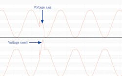
A “loose neutral” in a residential location can cause equipment damage and even a house fire. An open neutral may start as a high-resistance connection that shows subtle signs in waveform capture data before becoming more obvious as classic opposing voltage swells and sags in the strip chart.
An open or intermittent neutral is a serious problem in single-phase residential services. In a single-phase service, a 240V transformer winding includes a center tap, defined as the neutral point. The two ends of the transformer coil measure 120V (referenced to neutral) and are 180° out of phase, giving 240V between them. Any 120V load on either leg returns current through neutral, the center of the winding. If the two 120V legs have exactly equal loads, the neutral return currents from each leg exactly cancel out, resulting in no net neutral current. This is electrically equivalent to a single 240V load across both legs with no neutral interaction. Otherwise, the neutral current is the difference in load current between the two legs. Figure 1 shows an example with two loads — one on each 120V leg.
The computer is a 6A load; the light is a 4A load. The difference in current (2A) returns through the neutral. Each load sees 120V RMS. The center tap of the transformer in a sense forms a very stiff voltage divider, ensuring that each 120V leg is equal as referenced to that midpoint.
If a break in the neutral occurs (shown with the X marks in Fig. 1), then load return current cannot flow through the neutral. In this case, the loads are now in series with a 240V voltage source. Since they’re in series, the current through each must be equal. The low transformer impedance and center tap no longer form a midpoint. Instead, voltage across each load now depends on their individual impedances. In this case (assuming for the sake of discussion that they’re linear loads), the computer would have 4/10th of the 240V, while the light would have 6/10th — putting 96V on the computer and 144V on the light. The more unbalanced the loads, the lower the voltage on one leg and the higher on the other. If the loads happen to be well balanced, the condition can persist without causing many symptoms, especially if the neutral isn’t completely open.
Loose neutrals in RMS data
From above, the characteristic sign of the loose neutral is the RMS voltage in one leg rising, the other falling, and the total of the two legs roughly equaling the original total. The RMS sum of the two legs is unchanged because the full transformer coil is providing that voltage in either case. If the total load current is unchanged, then the voltage drop across the full transformer winding, service drop, etc., is also unchanged. It’s possible that the voltage swell in the high leg could cause a load to draw disproportionately higher current, in which case the total voltage may drop slightly.
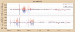
Instead of the neutral tap creating the two voltage legs, the voltage divider formed by the loads themselves define the two leg voltages. Unless the loads are perfectly balanced, the two legs will be unequal — one higher than the midpoint and one lower. An example of this situation is shown in Fig. 2.
This customized graph plots the RMS voltage Channel 1 min with the Channel 2 max on the top plot, and the Channel 1 max with the Channel 2 min on the bottom plot. This grouping makes it easy to spot simultaneous movements of both legs. There are many periods in Fig. 2 where the voltage max is over 140V, while the min dips to 100V. The sum is still 240V, the classic pattern of a loose neutral. Note that either leg may be the “high” leg — in Fig. 2, the high leg switches many times from Channel 1 to Channel 2, as specific load balance changes. For the RMS strip chart data to be useful, the loose neutral must persist long enough to change the RMS values appreciably. For very fast sub-cycle intermittent opens, or high-resistance neutrals, this may not be the case.
Loose neutrals in instantaneous (waveform) data
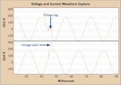
The fundamentals of voltage movements with a loose neutral are the same when viewing raw waveforms, but the presentation is different. With RMS values in the strip chart, a voltage sag is always a decrease in value, while a swell is an increase in value. With the instantaneous values of the sine wave, the specific direction of the voltage shift depends on which half of the voltage waveform is affected. On a point-by-point basis, the subtracted difference of one leg from the other at any specific point during the loose neutral is constant compared to the difference at the same point on the waveform during other cycles. Figure 3 shows an example of an open neutral waveform capture.
Here, most of the load is on Channel 1 and almost none on Channel 2. Consequently, the voltage on Channel 1 drops almost to zero, while Channel 2 increases to virtually the entire transformer output (240V RMS). The open only persists for 2.7 msec — less than a quarter of a cycle. The “one leg rises, one falls” is more complex in the waveform view. For a leg to “fall,” it must go closer to zero volts. Depending on the point on the waveform where the event starts, this could mean rising on the graph from a negative value toward zero or falling from a positive value. In Fig. 3, Channel 1 “falls” from negative voltage up to almost zero volts. To “rise,” a leg must increase in magnitude — further either in the positive or negative direction. Here Channel 2 rises by increasing from a positive starting point. If this event had happened in the negative half of Channel 2’s waveform, the “rise” would have been downward toward a more negative value.
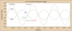
The arithmetic difference between the two legs at any point in time will be equal to the full 240V (RMS) transformer voltage across the entire winding. As shown in Fig. 4, the two 120V legs, measured with neutral as a reference on a point-by-point basis, combine via subtraction to equal the larger 240V waveform.
At any specific point on the waveform, the value of L1-L2 at that point is equal to the sine wave value of the 240V transformer output at that point. In Fig. 4, the point at time t = 15 msec is given for L1, L2, and the 240V output. L1(t) for an ideal sinewave is 99.8V, L2(t) at that point is -99.8V, and the full transformer output is L1(t)-L2(t) = -99.8 - 99.8 = -199.6V.
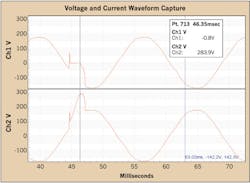
This relationship holds true during a loose or open neutral. In Fig. 5, the event from Fig. 3 is analyzed in more detail.
The point table is shown at a specific sample during the event. At point 713, or 46.53 msec, L1 is -0.8V, and L2 283.9V. Subtracting those values yields -290.7V for the full transformer output. Looking one cycle later (after the event), same point on the sine wave is at 63.02 msec. Here, L1 is -142.2V, and L2 is 142.3V. Both channels are equal and opposite, as expected. Subtracting L1 from L2 results in -142.2 - 142.3 = 284.5V, roughly the same as the 283.9V during the loose neutral event. Here, the criteria of one channel rising, one channel falling, and the difference remaining the same is met, indicating a loose neutral event. During the event, Channel 1 is mostly flat near zero volts (held there due to the low impedance of its load compared to Channel 2). Consequently, Channel 2’s shape is that of a 240VAC sine wave, since numerically both channels must sum to that waveform.
Final thoughts
Note that these patterns are often indicative of a loose neutral, but may not always present as such. Balanced loads, alternate current paths through a ground, etc. can hide the pattern of a loose neutral during a particular recording. However, in many cases with a persistent open connection the signs are visible in the RMS strip chart using the loose neutral graph. Before that happens, more subtle indications may be present in the waveform capture data that are not as obvious in the strip chart. For sub-cycle intermittent problems, the RMS value may not be altered enough to be noticeable in the strip chart. In these cases, the pattern may be spotted in waveform capture data while the problem remains at the sub-cycle duration, before it presents more serious symptoms.
Mullins is VP of engineering and operations for Power Monitors, Inc., Mt. Crawford, Va., where he has been pioneering change and advancement in power quality measurement for 22 years. He can be reached by email at [email protected].
