For an efficient design, the conductor ampacity tables in Chapter 3 of the National Electrical Code (NEC) provide a starting point. But did the installation stay efficient over time? One way to determine this includes the step of determining the voltage drop.
The longer your runs get, the lower the voltage is at the point of utilization. But not all of the difference may be due to voltage drop. Voltage drop is not caused by poor connections, bad contacts, insulation problems, or damaged conductors; those are causes of voltage loss.
It’s important to distinguish voltage drop from voltage loss. You can have both voltage drop and voltage loss in any circuit. You can calculate the voltage drop by using any of several accepted voltage drop formulas. Subtract the resulting number from the measured voltage decrease, and you have voltage loss.
Let’s say you have a 480V feeder. At the breaker, you measure 478V. That’s within the normal range for a nominal 480V system. The feeder supplies a transformer clear across of the building. There, you measure 460V. Is this good or bad in relation to trouble brewing?
You really cannot know until you calculate the voltage drop and then determine the voltage loss.
Using a standard formula for three-phase voltage drop, here’s what you do:
Step 1: Multiply I x L x R x 1.73, where (I) is the current, (L) is the conductor length from supply to load, (R) is the constant for the conductor material (e.g., 12.9 for copper), and 1.73 is the 3-phase multiplier.
Step 2: Then, divide that by the circular mills of the conductor.
Once you do the multiplication, divide the new number by the circular mils of the conductor. Many pocket reference guides provide a chart of conductor circular mils, but so does the NEC. It’s Table 8 in Chapter 9.
In our example noted above, we have an 18V difference. But suppose in this case you calculate a voltage drop of about 8V. That means about 10V is because of some deficiency or deficiencies in that circuit (and/or its connected load). The voltage drop itself is less than 2.5%, so it’s within the guidelines for feeders, but that does not mean all is well.
You can’t simply ignore the other 10V because it’s not voltage drop or because it’s insignificant in relation to 480V. When above a volt or two, voltage loss is the proverbial canary in the mine. Below that level, the difference can reasonably be attributed to acceptable impedances in connections and is probably not an issue.
Voltage drop is a fixed condition; voltage loss is nearly always a deteriorating one. This means if you measure a voltage differential greater than the voltage drop, you should find what is causing the additional amount (unless it’s only a volt or two). The higher the voltage, the more likely you have one or more connections moving toward failure.
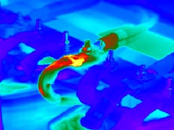
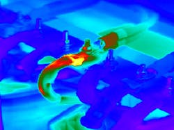
A good first step is to get out the infrared camera and check all connections on this run. Then disassemble and replace any bad ones (don’t just “retighten” as that will only make things worse by reducing the clamping power of the fasteners). If you still measure more than a volt or two above the calculated voltage drop, further troubleshooting is wise.
You might, for example, look at the contact resistance across safety switches, contacts, fuses, and circuit breakers. Any of these can produce a voltage loss. And if it’s in one place, it is likely in another (for the same reasons it exists in the first) so don’t stop with the first one you find and think you found “the problem.”
Voltage loss due to high contact resistance also may be load-related. For example, if the contact pressure depends upon a spring, it can get worse over time. High resistance = high heat = weakening of springs, and so on.
About the Author

Mark Lamendola
Mark is an expert in maintenance management, having racked up an impressive track record during his time working in the field. He also has extensive knowledge of, and practical expertise with, the National Electrical Code (NEC). Through his consulting business, he provides articles and training materials on electrical topics, specializing in making difficult subjects easy to understand and focusing on the practical aspects of electrical work.
Prior to starting his own business, Mark served as the Technical Editor on EC&M for six years, worked three years in nuclear maintenance, six years as a contract project engineer/project manager, three years as a systems engineer, and three years in plant maintenance management.
Mark earned an AAS degree from Rock Valley College, a BSEET from Columbia Pacific University, and an MBA from Lake Erie College. He’s also completed several related certifications over the years and even was formerly licensed as a Master Electrician. He is a Senior Member of the IEEE and past Chairman of the Kansas City Chapters of both the IEEE and the IEEE Computer Society. Mark also served as the program director for, a board member of, and webmaster of, the Midwest Chapter of the 7x24 Exchange. He has also held memberships with the following organizations: NETA, NFPA, International Association of Webmasters, and Institute of Certified Professional Managers.

