Why PV Inverter Failures May Lead to AC Power Quality Issues
Even though inverters have been steadily improving in reliability, they are still the most common point of failure in a photovoltaic (PV) system. Inverter failures could be related to infant mortality, installer error, or age and wear. Roughly 34% of inverters fail within the first 15 years of installation, according to a 2022 paper by Christof Bucher, Jasmin Wandel, and David Joss titled “Life Expectancy of PV Inverters and Optimizers in Residential PV Systems.” But what happens when they do fail — is it a simple swap out and replace? Or can there be other unforeseen issues?
Changing damaged devices is straightforward and shouldn’t require significant troubleshooting. But the product overview and case studies presented in this article show that, even today, there is still room for improvement in current designs — and lessons from the past should be rolled into all future designs. This piece will demonstrate how failures in grid-tied inverters can lead to more costly repairs.
Current inverter designs
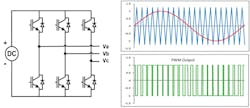
Due to the pressure for smaller and more cost-effective machines, most string and micro inverters are transformer-less inverters or those that contain no galvanic isolating devices to separate the DC and AC conversion components. These inverters contain a network of switches that are turned on and off at specific intervals to create a pseudo sine wave, as explained in “Harmonics and Noise in Photovoltaic (PV) Inverter and the Mitigation Strategies” at www.solectria.com.
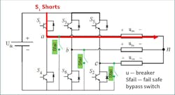
Failures in this switching network can have a catastrophic impact on the inverter circuits as well as the DC components upstream and the AC components downstream. Manufacturers include failsafe and/or bypass blocking switches to provide an electronic equivalent of the galvanic isolation found in transformer-based inverters. This switch network, when designed properly, separates the AC and DC currents during operation and in the event of a failure. The DC circuit elements (PV modules) should never directly interact with the downstream AC panelboards and breakers (Fig. 1).
How do these switches work? In the event of a switch network failure, the inverter will shut down and either block or short the DC current to ground or common. In Fig. 2, these switches are labeled “Sfail.” In this topology, the switches would be turned on, and the DC current would be shorted back to the PV modules during the inverter shutdown. Proper design would dictate that, in the event of a switch network failure, other elements in the circuit are protected, and damage to infrastructure or other adjacent equipment is minimized.
But what happens if the designs are less than optimal or are missing the necessary failsafe switching? Inverter failures can be quite catastrophic to the internals of the machine, releasing a lot of energy into a confined space. Once struck, a DC arc won’t extinguish until the voltage required to maintain the arc is exceeded, as noted in the 2024 IEEE paper “Modeling the Dynamic Behavior of DC Arcs” by L.B. Gordon. In an event where the inverter failsafes are absent, improperly designed, or overloaded, it may be possible for DC current to contact the AC bus for a short period of time while that arc is still in process. This would be a worst-case situation and is a condition that the AC panelboard and breaker manufacturers do not design for.
Lessons learned from case studies
The cases outlined here reveal that several inverter manufacturers have either improper or inadequate failsafe switch networks that directly contribute to power quality (PQ) issues in several AC panelboards. To better understand these issues, a closer look at how the failures were found, propagated, and ultimately resolved is in order.
Upon commissioning a PV array or system, several electrical and mechanical checks are performed to verify the safety and installation of said system(s). If a component fails, it is usually promptly replaced after troubleshooting of the existing hardware to ensure that other components were undamaged by the failure. In this case study, failed inverters caused hard-to-detect damage to the molded case circuit breakers in the switchgear that went undetected by the technicians performing the repairs.
To understand the subsequent failure mechanisms, we provide an outline of the fault and progression here. An inverter fault occurs — specifically, a transformer-less model’s switch network fails or burns up. This trips the inverter’s AC breaker, and the repair personnel sent to respond see that the inverter doesn’t power up. The associated AC breaker may exhibit visible charring, smoke, or damage.
However, breaker damage is not always obvious to repair personnel. They swap the inverter with a new unit, close the breaker, and re-commission the replacement inverter. Upon power-up of the replacement inverter, it will likely turn on and seem to operate normally. In some cases, the AC breaker may smoke or refuse to close, or the new inverter may power up and then immediately shut down due to a PQ fault.
The most confusing case is when the inverter seems healthy, but inverters on adjacent circuits start to show fault codes. It was in this state that we first discovered the underlying problem. One site had a history of inverter faults, including chronic PQ issues and a very high inverter failure rate. At this site, more than 50% of the inverters failed/required replacement over a four-year period. Subsequently, the AC breakers at this site also needed to be swapped out due to PQ issues, as outlined below.
These PQ issues could extend to all inverters or just a subset connected to the same AC panelboard. As the inverters are allowed to run, the problem tends to get worse. Why? To answer this question, we need to understand a bit about power quality, and, more precisely, distortion.
Power quality is the measurement of how perfect the AC current and voltage sine waves are. The measurement is called total harmonic distortion, or THD. The amount of distortion is regulated by several standards that describe how the PV inverters interact with the AC grid. These standards — IEEE Std 929-2000 and UL 1741 (the inverter qualification standard) — set the limit to less than 5% distortion. If an inverter measures more than 5% THD, it may shut down and disconnect from the AC bus until either the THD drops below that 5% level or a fatal fault is detected. Figure 3 shows an example of a sine wave with 5.7% THD.
Understanding how an inverter reacts to distortion helps determine other potentially damaged components. Increased THD can cause heating in breakers, transformers, and fuses, causing them to prematurely fail. In the case of our study, the increased distortion was caused by an increase in impedance across the inverter’s associated AC breaker. How could breaker contacts create increases in sine distortion?
The shorting of the inverter switching network allowed a DC current to flow from the PV arrays through the switching network where they ultimately contacted the AC breaker. Breakers designed for AC bus and panelboards are not designed for DC currents — even for a short amount of time. Ultimately, the breaker will trip and clear the fault, but it may damage itself in the process. When we examined the system, we found that the breakers had “seen” high DC currents, possibly for extended periods, as the breaker poles arced for the duration of immolation of the inverter switching network. This caused excessive arcing and heating in the breaker switching elements, which resulted in the breaker’s impedance characteristics changing, generally by increasing per-pole impedance.
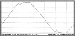
Breakers designed to interrupt AC currents are designed differently from their DC current cousins, which require special considerations for opening or extinguishing a circuit. Because AC power has a zero crossing every 8.33 msec in 60-Hz systems (Fig. 4), as outlined by C. Lei and W. Tian in “Probability-Based Customizable Modeling and Simulation of Protective Devices in Power Distribution Systems,” it allows for simpler mechanical interrupting devices using thermal or thermal-magnetic properties to open an over-current condition. DC arcs, however, need to extinguish,” either via their voltage exceeding that required to maintain the arc, or by being extinguished using a “magnetic blowout device,” like the one shown in Fig. 5, reprinted with permission from the Journal of the American Institute of Electrical Engineers from the 1922 paper “Air-Break Magnetic Blow-Outs: For Contactors and Circuit Breakers Both A-C and D-C.”
This device is used in parallel with a mechanical trigger to interrupt the current flow and extinguish the arc between poles. Most breakers designed for AC service do not contain such a device, nor is their design sufficient to rapidly burn out a DC arc. This is one reason why breakers rated for both DC and AC service have substantially smaller current ratings when operated under purely DC currents.
What happened to the AC breakers in our PV fields? Although the makes, models, and descriptions of the MCCBs in this study have been removed and scrubbed from the data shared here, these breakers are from well-known, prevalent manufacturers. Breakers recovered from the sites exhibiting PQ issues were tested for resistance and impedance. Failed units were visually imaged using X-ray and physically disassembled and inspected for damage. All breakers examined displayed a higher impedance when compared with a factory-fresh device. Each pole was measured to determine whether a pattern could be seen in the limited sample set.
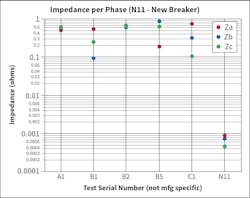
All breakers showed higher per-pole impedance compared to a new, stock device. The impedance across the damaged breaker poles with the breakers closed showed a 10 to 100 time increase in resistance compared to known good breaker poles. Figure 6 shows five damaged breakers (A1, B1-3, and C1) and one known good example (N11). Measurements were taken using a stock inductance, capacitive, and resistance (LCR) meter, set up for 60-Hz frequency response. Resistance values were validated using a standard milli-ohmmeter.
The new/good breaker showed less than 1 milliohm of impedance per pole, whereas faulty poles measured between 0.01 and 1 ohm (100–1000 milliohms), as shown in Fig. 6. Additionally, the resistances were not all the same within the same breaker, with B1, B5, and C1 showing per-pole resistances varying by as much as 10x between poles.
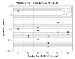
By modeling the impedance in terms of voltage drop, using measured values in Fig. 6, we can calculate voltage drops of 10VAC with an assumed load of 150A, as shown in Fig. 7. Voltage drops of 10VAC or more across the breaker contacts will result in an increase in THD. If the distortion levels increase beyond a few percent, sensors in the inverter will flag a PQ fault and will shut down the unit to protect the electronics from damage.
These results explain why some of the breakers were not obviously damaged or “crunchy” in operation, but still created issues. When the voltage drop is small per phase, the standard infrared (IR) thermographic imaging does not show an overheated breaker. However, the voltage drop across the breaker is no longer balanced between phases, creating a small phase imbalance at each breaker. Three-phase systems need to be as symmetric and balanced as possible to provide clean power, and voltage or current imbalance in the breaker phases can propagate into higher distortion levels.
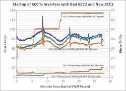
Looking at real circuit waveforms of voltage and current in the AC panelboard, we can see that, immediately after the inverter failure, there is significant harmonic noise on the AC bus. After the breaker is swapped out, the noise drops below the 5% threshold required by code (Fig. 8). This data was gathered with a power quality meter at two locations on an operating PV site — both before and after breaker replacement.
Multiple inverters on this site showed component detachment in the harmonic filter section due to melted solder joints, indicating substantial overheating. These units had “heat sink” temperature monitoring via supervisory control and data acquisition (SCADA), which never showed an excessive operating temperature. After replacing all the breakers on the site (35 in total), the harmonics completely vanished. We suggest that when a transformer-less inverter experiences a catastrophic failure and requires replacement, the breaker attached to the specific inverter should also be replaced to avoid this problem.
Failure to replace a single damaged breaker can begin a process that one of the authors has dubbed “breaker cancer,” whereby increased harmonics on a site drive further overheating and damage to inverters, which can cause further breaker damage. This was the case on the site from which the data in Fig. 6 was gathered. Prior to our involvement, this O&M subcontractor had filed multiple warranty claims with the inverter manufacturer, upgraded the firmware multiples times, and tried all manner of other things. This site showed no visible damage to any of the breakers, and normal multimeters on a site are not sensitive enough to measure the milliohm-level variance between breaker phases that is easily detectable with laboratory-grade measurement equipment.
Devices used to extinguish DC currents, called magnetic blowout devices, have been shown in many studies to provide significant reduction in arcing and faster breaker opening times in DC systems. Designers of AC breakers do not expect the devices to experience DC currents; thus, they usually don’t include magnetic blowout devices. If AC breakers installed in PV or on circuits with inverter switching topologies contained DC magnetic blowout devices, they wouldn’t become damaged or be subjected to overheating.
Conclusions
AC MCCBs are generally not equipped with DC arc blowout devices, as it is not an expected operating mode. They may, however, contain arc chutes or deflector devices, as in the case of at least one device we opened for this study. Arc chutes are used to direct or channel the extinguishing arcs during the normal make/break operations and will do little or nothing to help reduce the arcing under DC current. Understanding how failures in DC-to-AC inverters, AC panelboards, and breakers propagate is key to ensuring that failures are contained and predictable.
Renewable energy is not the only industry that uses transformer-less inverters, nor is it the only industry that has seen these types of failures. Any transformer-less inverter that interacts with an AC bus is susceptible to these failures. Safeguards need to be designed into the architecture of the switching network to prevent catastrophic failures and equipment damage and to reduce the possibility of worker injury.
Work has been done in the PV inverter field to design failsafes and proper shutdown of damaged circuits. Unfortunately, several manufacturers are not implementing these designs in a robust manner. Although not required by current codes and standards, it would be a good practice for AC panelboard and breaker manufacturers to add or include proper DC arc extinguishing mechanisms to MCCBs. Until all manufacturers properly design and account for this failure mode in transformer-less inverters, the failures and related PQ issues outlined in this study will continue to plague the renewable energy sector as well as other industries where transformer-less inverters interact with the AC grid (uninterruptible power supplies (UPSs), for example).
Acknowledgements:
This work was authored in part by Alliance for Sustainable Energy, LLC, the manager and operator of the National Renewable Energy Laboratory for the U.S. Department of Energy (DOE) under Contract No. DE-AC36-08GO28308. Funding provided by the U.S. Department of Energy’s Office of Energy Efficiency and Renewable Energy (EERE) under Solar Energy Technologies Office (SETO) Agreement Number 30295. The views expressed in the article do not necessarily represent the views of the DOE or the U.S. Government. The U.S. Government retains and the publisher, by accepting the article for publication, acknowledges that the U.S. Government retains a nonexclusive, paid-up, irrevocable, worldwide license to publish or reproduce the published form of this work, or allow others to do so, for U.S. Government purposes.
About the Author
William Sekulic
William Sekulic earned a BSEE from Colorado School of Mines. He has been a member of the NREL PV Reliability Group since 2001. Along with his research duties, he is a member of the NREL Electrical Safety Committee, a part-time electrical safety officer, a senior member of IEEE, and a registered professional engineer in the state of Colorado. His experience includes power systems, radio transceivers, emissions monitoring equipment, PV inverters, energy storage systems, and data acquisition.
Greg Linder
Greg Linder has an MSEE from Clarkson University and a BSEE from the University of Illinois. Mr. Linder has worked in SCADA for renewable energy systems since 2007. He is a member of IEEE and is a registered professional engineer in Colorado. Mr. Linder founded SolarSCADA in 2008 and is now SVP of hardware design at Skyfri Corp, following their acquisition of SolarSCADA in 2022.
