Harmonic distortion is not a problem unless it becomes a problem. Harmonics are a breakdown of a distorted waveform into its separate frequencies, which are integer multiples of the fundamental frequency. For example, a nonlinear load operating on a 60-Hz system can create harmonic currents at 180 Hz (3rd harmonic), 300 Hz (5th harmonic), and so on. Initially, the magnitude of these individual harmonic frequencies is typically small in comparison to the magnitude of the fundamental frequency (60 Hz). However, it is possible for the system to amplify the magnitude of the harmonics if the system is unintentionally tuned to a harmonic frequency.
An electrical circuit that contains inductance and capacitance can create an electrical characteristic called resonance. Simply put, resonance occurs when the inductive and capacitive reactance values are equal on the circuit. The point of interest or study is typically at a bus where the harmonic source is connected or any other bus that has equipment sensitive to harmonic distortions.
There are two types of resonance: series and parallel. The result of a series resonance is low impedance. If the harmonic source produces a current at the same frequency as the series resonance frequency of the system, then the low impedance will allow higher current to flow at that given frequency. The additive current from the fundamental frequency and the resonance frequency raises the effective current’s magnitude to a point where it can cause fuses to prematurely blow and electrical equipment to overheat. A parallel resonance creates a high impedance and raises the voltage magnitude within that resonance frequency. The resonance voltage distorts the fundamental voltage waveform, which is seen by all the devices on the circuit.
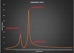
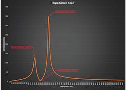
To identify where the resonance frequencies reside, perform an impedance scan on a simulated circuit, utilizing the aid of a software tool that performs this task.The tool will inject a unit current at different frequencies and plot the circuit’s impedance as seen from the point of interest. This is helpful in identifying if the circuit topology will amplify the harmonic magnitudes and at which frequency. This information can be used to assist in detuning the circuit away from the resonance frequencies by way of harmonic filters. Another method is to reconfigure the circuit’s topography by moving the power factor (PF) correcting capacitors, or other devices, to a different electrical location on the circuit. This effectively alters the impedance values between the devices, which would shift the resonance frequencies. However, if there are no harmonic currents injected into the system, then there is nothing to amplify.

