Understanding power factor (PF) is important because it gives us a clear understanding of the efficiency of an electrical system. Put simply, it’s the ratio of true power and apparent power, which represents how much power supplied by the source will perform useful work. A unit-less number used in alternating current circuits, PF can be used to refer to a single piece of equipment (such as an induction motor) or for the electricity consumption of an entire building, facility, feeder, etc.
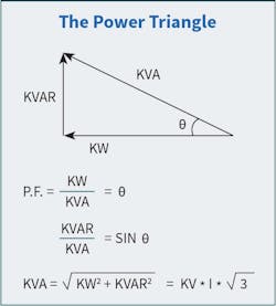
When the PF is 1.0 (called unity), it means that the resistive load will consume all the power supplied by the source and convert it into another form of useful energy. If the PF is 0.0, it means all the power from the source is entirely reactive and will be stored in the reactive load and returned to the source. See the Equation on the right.
A common analogy used to explain PF is a nice cold pint of beer. We pay for a beer by the glass, but inside the glass, there is both beer and foam. The more beer we have, the less foam there is — so we get good value for our money. If there is a lot of foam, then there’s not a lot of beer — and we’re not getting good value for money. The beer represents our true power or kilowatts (kW). This is the useful stuff we want and need. This is what does the work. The foam represents our reactive power or our kilovolt-amps reactive (kVAR). This is the useless stuff. There will always be some in the glass, and we have to pay for it. However, because we can’t use it, we don’t want too much of it. The combination of kW and kVAR is our apparent power or our kilovolt-amps (kVA).
A perfect PF would be 1.0 or unity, but except for a purely resistive load, this would be counterproductive because that will create resonance. A good PF would be 1.0 to 0.95. An acceptable PF is between 0.95 and 0.8. Anything below 0.8 needs improvement or power factor correction (PFC). The Figure has some useful formulas and the most common representation (power triangle).
What causes a low PF? Certain equipment is highly inductive and sources of reactive power (kVAR), including:
- Transformers
- Induction motors
- Induction generators
- HID lighting
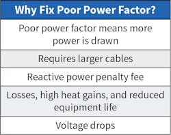
These types of indicative loads can constitute a major portion of the power consumed in industrial complexes. Improving the PF can maximize current-carrying capacity, improve voltage to equipment, reduce power losses, lower electric bills, and avoid PF penalties (typically occurring below 0.9 PF), as shown in Table 1.
When the PF is low, this means that the electrical system has low efficiency. The major effects of low PF are:
- The system would draw a much higher current for real and reactive power, which increases line losses and hence the heat.
- Larger conductor sizes and switch gears are required to compensate for the line losses, which make this a costly exercise.
PF correction
he simplest way to improve PF is to add PF correction capacitors to the electrical system. PF correction capacitors act as reactive current generators, helping to offset the non-working power used by inductive loads, thereby improving the system PF. The interaction between PF capacitors and specialized equipment, such as variable-speed drives, requires a well-designed system.
The most practical and economical PF correction device is the capacitor. It improves the PF because the effects of capacitance are exactly opposite those of inductance.
The VAR of kVAR rating of a capacitor shows how much reactive power the capacitor will supply. Since this kind of reactive power cancels out the reactive power caused by inductance, each kiloVAR of capacitance decreases the net reactive power demand by the same amount. A 15-kVAR capacitor, for example, will cancel out 15 kVA of inductive reactive power.
Capacitors can be installed at any point in the electrical system and will improve the PF between the point of application and the power source. However, the PF between the load and the capacitor will remain unchanged. Capacitors are usually added at each piece of offending equipment, ahead of groups of motors (ahead of motor control centers or distribution panels), or at main services.
PF correction capacitors can switch on every day when the inductive equipment starts. Switching a capacitor on can produce a very brief over-voltage condition. If a customer has problems with variable-speed drives turning themselves off due to over-voltage at roughly the same time every day, investigate the switching control sequence. If a customer complains about fuses blowing on some (but not all) of their capacitors, check for harmonic currents.
There are two types of capacitor banks: fixed and switched. A fixed bank is connected all the time and continuously supplies reactive power (VARs) into the system to compensate for a low PF. The downside of a fixed bank capacitor is that during periods of light load (i.e. nights, weekends, etc.) this additional compensation can produce higher than normal voltages, which can be damaging to sensitive electronic equipment.
A switched (or automatic) capacitor bank monitors the electric service continuously and switches on the capacitors only when needed. This type of system prevents damaging overvoltages and improves the PF to unity (1.0). The intelligent controllers of switch capacitor banks use a voltage override feature to disconnect the capacitor bank if the system’s primary voltage is too high.
Installation example
A large manufacturing facility was receiving electric utility penalties for poor PF. The facility was fed through a 2,000 kVA transformer to a 3,000A, 480V main switchboard. When the PF fell below 0.9 lagging, the electric utility switched demand billing from kW to kVA, which can increase the demand charge significantly. This can be seen in Table 2, which shows a summary of the facility’s maximum, minimum, and average demand (kW and kVA) and PF.
As can be seen, with a PF below 0.9 and a switch to kVA demand from kW, the increase can be several hundred kW/kVA each month, costing the facility significant money. Based on a reactive power range of 424 kVAR to 898 kVAR during the 12 months of metering, three different sizes of capacitor banks were evaluated: 300 kVAR, 450 kVAR, and 600 kVAR. For each, it was calculated as to what the reactive compensation would be, as summarized in Table 3.
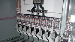
The 600-kVAR capacitor bank would correct the PF to near 1.0 but would cause the facility to go leading PF during periods of light load. This option wasn’t recommended due to the possibility of voltage rise/increase. It is recommended that a 450-kVAR capacitor bank be installed, which will improve the building PF from its present range of 0.78-0.91 to 0.96-0.99. This improvement in PF will reduce the flow of reactive power (VARs) into the building and allow more real power (watts) to flow from the transformer. A switched capacitor bank in 50-kVAR increments was recommended to better regulate the PF as the facility load increases or decreases, as shown in the Photo.
Financial payback for an installation of a PF correction bank can be on the order of only on to two years, depending on the penalties being assessed for low PF.
About the Author

David Colombo
David Colombo, P.E. is a Professional Engineer located in Massachusetts, and the owner and principal of Power Engineers, LLC, a design, engineering and consulting firm. He has over 30 years in the electrical engineering and construction industry and is involved with the design of utility substation & distribution infrastructure, large scale renewable energy projects, and commercial / industrial power systems. He specializes in the areas of medium-voltage design, power distribution, protection, metering, power quality, power studies and, arc flash analysis. He also provides owner’s engineering support for developers, EPC contractors and project owners. Prior to starting Power Engineers, LLC and being an engineering consultant, he was a utility distribution supervising engineer. He holds a Bachelor of Science degree in Electrical Engineering from Worcester Polytechnic Institute (WPI) and a Master of Engineering degree in Electric Power Engineering from Rensselaer Polytechnic Institute (RPI). He is a Registered Professional Engineer in 13 states.


