Hospitals and data centers have always been considered critical facilities. In light of the recent COVID-19 pandemic, however, that concept has taken on a whole new meaning. Identifying and mitigating power quality issues help to ensure these facilities continue to operate 24/7 during this unprecedented crisis. Therefore, devising a systematic approach to identify power quality issues and reduce unexpected outages is more important than ever before.
Commercial and industrial clients commonly request testing support when faced with undesired equipment operation. Power quality issues can cause mechanical or electrical defects that often remain undetected, while a facility spends capital repairing or replacing the damaged equipment. Such issues could cause a complete overhaul of machinery during a production cycle or power loss in critical circuits for a hospital.
Power quality issues essentially include fluctuations in the power supply to equipment, such as voltage sags, spikes, and harmonic disturbances. To discover if power quality is the culprit behind an equipment failure or repair issue, the first step is to understand the frequency, timing, and persistence of the problem, since the results of power quality issues may only show up during particular usage patterns or system loads.
Some questions to consider include:
- How often has it happened?
- Did it occur at a particular time of day or when other equipment was noticeably in use?
It’s also important to assess the damage as it stands and gather information about previous damage or problems to compare, if possible. Initial assessments are fundamental, and the more information the better. For example:
- Is the equipment operational (or partially operational)?
- Are there obvious signs like burns or permanent discoloration on the equipment, or less obvious signs of undesirable operation?
With information in hand, a recommended testing procedure is the next step to diagnosing the problem. There isn’t a “one-size-fits-all” troubleshooting method. However, to address undesired operation in an electromechanical system, understanding the three fundamental states of electromechanical systems is key to a qualified tester’s systematic approach: transient, steady-state, and decay. The duration of each state varies based on the type of system. Both transient and decay states have a short duration, whereas steady-state operation constitutes the bulk of the equipment duty cycle. All the energization and de-energization processes in an electromechanical system produce a transient response in voltage, current, or frequency.
Understanding power quality
Power quality is defined by the Institute of Electrical and Electronic Engineers (IEEE) as providing power and grounding to sensitive equipment in a manner that is suitable to their operation. Transient responses happen in every system because of the physical inertial laws of nature. An object at rest tends to stay at rest, unless an external force is applied. For power systems, a de-energized transformer’s magnetic core will not experience a sudden magnetization unless voltage acts on its primary or secondary winding. Once the transient has occurred in an electrical system (typically lasting up to 20 cycles in electrical operation), the electrical devices reach steady-state operation.
Steady-state refers to the equilibrium of the electrical system, when the generated power is transferred to the load without the bouncing of energy back and forth between the source and load. Transient operation happens when the load changes, such as during the startup process of electric motors and the switching of electronic loads equipped with rectifier circuits.
Knowing what to look for
First, it is essential to ask what the responsible person on-site believes is the cause for the undesired trip condition and the type of load fed through the protection that tripped. Determine if the type of equipment is a motor or a static device — and if it is equipped with power electronics (IGBTs, SCRs, etc.) that control the equipment.
Second, determine if a similar event could recur or if a tripping action has caused a lockout in the electrical system. If a lockout has been activated, don’t suggest resetting the protection. That could cause damage to the equipment. Instead, it’s recommended to ask if insulation resistance has been tested on the equipment and inspect for visible damage, if any.
Third, ask if this is the first time this event has occurred and if there is any record of prior occurrences. This information will be important in determining if the issue is an ongoing part of the dynamic behavior of the system.
Now that we’ve explained the analysis techniques/steps you should follow when investigating a power quality problem, let’s move on to a real-world case study in which these concepts were employed.
Power quality assessment approach
This case study involved a client who requested a study after variable-frequency drives (VFD) tripped during normal operation. Some actions had been taken to avoid the undesired tripping, and the ground fault protection was disabled for the VFD. The client was very concerned that the protection was disabled. To understand why the system was underperforming and re-enable ground fault protection, the client needed to know if higher ground currents (leakage currents) were the actual cause of the trip events.
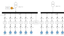
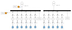
An evaluation was conducted during regular business hours over a day-long period of normal operations. A true measurement of the dynamic load behavior of a facility was required to properly capture the information needed. Meters were set for power variable logging in order to capture any significant changes. Two power quality (PQ) meters with a 200-nanosecond (nsec) resolution were connected in two separate locations (Fig. 1):
- Meter PQ1 was installed at the load side of the transformer that feeds Bus MR1.This location was modified when analyzing drives connected to Bus M1. Meter PQ2 was installed on the line side of the VFDs.
- Drives were de-energized and ramped up from 20-Hz to 50-Hz operation. Measurements on the VFD load side were taken simultaneously with a clamp-on meter and read from the human machine interphase (HMI) device of the VFD. This procedure was repeated for each VFD that exhibited undesired operation.
- Finally, the maximum load was cycled to Bus MR1 connecting all the drives and loads, and the process was repeated for Bus M1.
Figure 1 depicts the system and the location for the PQ meters during the first assessment. Similarly, PQ2 was moved to monitor each one of the loads ― in this case VFDs ― that presented undesired tripping conditions.
It is important to mention that the selected procedure implicitly allowed the visualization of the impact of the drive on each feeder and main. The selection of drives to monitor during the tests were based on the client noting the number of events when the VFDs tripped.
After connecting PQ meters, it is important to consider the control aspects of a VFD. This electrical component is commonly used to operate motors (induction machines) measured in scalar volts per Hz control (V/Hz). With this control technique, the torque is maximized in the machine by varying the frequency and voltage of the source and operating the machine at almost constant torque on speeds up to nominal without saturating the motor cage of the machine or adjusting the voltage applied to the unit.
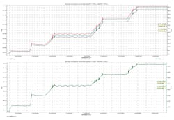
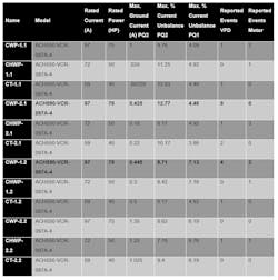
Measurements were taken at the load side of the VFD during the frequency ramp-up as seen in Table 1. Additional measured values over the ramp-up period include the phase and ground currents, total harmonic distortion (THD), phase-to-phase voltage at PQ2, and the harmonic spectrum at both PQ meters. These values were recorded to help identify what defects were occurring in the system and why they were occurring. The data are shown in Table 1, Table 2, and Figs. 2, 3, 4, and 5. All values are summarized in Table 3. The measurements were taken for each VFD, but the data for only one is shown. Table 3 allows for easier assessment of the evaluations run and the results of all the data gathered.
By following the test steps above for each VFD, Figs. 2 through 5 were created, allowing for comparable results for all VFDs. By incrementally ramping up the frequency through the test, how the frequency and speed of the machine affected the currents could be studied. The data points can be stacked on the same graph to more easily show where unbalances exist, such as the approximately 5A difference between Phase A and Phases B and C on Fig. 2. Figures 2 through 5 show the concepts of transient and steady-state well, and show why the tests were performed the way they were. The graphs show how the system handles the transient (the short, dense ripples), how the system responds (the sloping portions), and what happens to the system in steady-state (quasi-flat lines). Notice that the ground current follows the same shape as the phase voltages. Also notice in Fig. 2 and Fig. 3 that there are still some small fluctuations in steady-state for some voltages, which may indicate harmonics. In Fig. 5, a similar visual comparison can be made for how much of each harmonic is present in each phase, which further helps to show the unbalances.
Taking VFD CWP-2.1 as an example (shown in figures, tables, and in bold in Table 3), we see a current unbalance of 12.77%, which is one of the highest recorded for this system. It also has a high current unbalance on its corresponding feeder at 4.46% and a high ground current of 0.42A during the test. The manufacturer recommends that the line input current to the VFD should not vary by more than 3%. This VFD exceeds that recommendation. Though high, the ground current is below the 2% standard value for ground leakage.
The main conclusion that can be drawn from analyzing Table 3 is that there is a correlation between high, unbalanced current percentage and the ground current associated with these events. As the frequency increases and the machine speeds up, there is more ground current flowing in proportion to the frequency (Fig. 2 and Fig. 3).
With data and analysis in hand, the team could recommend procedures to identify and eliminate system defects, improve system performance, and prevent future events. The first recommendation: Verify the balance of the loads on the system and lower the current unbalance percentage. Leaving the unbalance could lead to de-rated power cables, increased losses, increased cost, and decreased efficiency, among other negative effects. Second, verify the unbalance levels seen on the VFD line side during the ramp-up with the manufacturer, as the unbalance creates an abnormal loading condition for a low-voltage drive. The VFD may treat the unbalances in current as a phase fault and can trip on earth fault or missing phase fault, which the client’s log showed multiple instances of. Finally, verify the high ground leakage currents in the downstream motors to detect any small insulation breakdowns, especially since there’s a record of previous fault conditions.
Final thoughts
The above scenario demonstrates how a power quality issue could be resolved. In this case, some of the most useful information came from the log of events provided by the client. This log allowed the identification of the problem VFDs and motors, the type of event (trip, overvoltage, etc.), and how many times the events had occurred. Without that starting data, it would have been much more difficult and time-consuming to find and diagnose the problematic VFDs. Because there is no “one-size-fits-all” solution, it was important to study the system and determine a testing procedure that would allow the most effective results to be gathered, and then consistently apply that test for each branch. For this system, there was high current imbalance and ground leakage proportional to the speed.
A client with a mysterious system defect issue may seem like a daunting task to tackle, but with a structured approach to the process and knowledge of the three fundamental states of power quality, the task may be cut down to a more manageable size. By finding the root cause, you can help your client avoid further repair cost and downtime.
Shrader is a project engineer and NETA II electrical test technician and Hughes is a project manager and NETA III electrical test technician with ABM Electrical Power Services in Raleigh, N.C.
