Uncovering Common Power Quality Misconceptions
By PBE Engineers
The type and number of electronic loads in customer facilities are truly the cause of a growing number of power quality (PQ) problems. Inevitably, the increasing complexity of these loads — further compounded by the increase in electric vehicle (EV) chargers, the onset of artificial intelligence (AI)-based data centers, and a rise in the number of distributed generation (DG) sources to power customer facilities — will cause further increases in electric utility and customer-based PQ problems.
While specific electrical engineering science must be applied to properly understand, identify, solve, and prevent PQ-related equipment problems in any customer environment, the art of conducting a PQ investigation involves addressing common misconceptions or myths associated with planning and executing an investigation. Doing this will help ensure information critical to the problem is not overlooked.
One must think outside the box and consider all potential causes and how they might be interrelated. Causes associated with the energy source, wiring and grounding system of the facility (and external infrastructures), and the electronic loads must be considered as a complete system. Not all disturbances cause PQ problems — only those that cause the wiring and grounding system and loads to act up should be considered. One can be assured that some of the causes (and interrelationships) when assembled to understand the dynamic nature of the problem will seem farfetched.
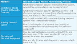
As a seasoned PQ investigator for more than 30 years, these two PQ problems described in this article are among the most bizarre scenarios one engineer has encountered over his PQ career. As one gains various types of PQ experience, such as conducting PQ testing, forensics, investigations, and standards development, we’ve learned facing such scenarios head-on makes a good investigator. This article walks readers through two case studies at customer facilities where common misconceptions were hard at work to derail the PQ investigator. Refer to Table 1 for the right questions to ask for guidance on addressing common PQ problems.
Scenario #1. Malfunctions and Failures of a Programmable LED Lighting System at a Major Airport
Security and safety in air transportation facilities depend heavily on quality power, especially in a fast-paced global society. To improve security and safety as well as reduce energy consumption in a major U.S. airport, more than 4,000 programmable electronic LED drivers in overhead luminaires were installed along each beam at the top of two new large canopies covering the main passenger entrance at both main passenger terminals (Photo).
During canopy construction and after commissioning the lighting system, many LED luminaires began malfunctioning (e.g., flashing, flickering, changing colors, etc.) with some failing to illuminate. These problems were very noticeable and could have distracted vehicle drivers and pilots. Aside from the degradation in the illumination level under the canopies, these problems also affected programmed scenes for holidays and special event displays visible to ground and air travelers. This problem presented some very unusual challenges.
What made this investigation unique?
Investigating PQ problems involving programmable LED lighting equipment can be challenging in any situation. What made this specific situation so bizarre? Following is a list of conclusions derived from troubleshooting, diagnosing, and resolving the underlying PQ issues.
- Highly reliable and quality power from the electric utility's network underground system was delivered to the airport campus, including the main terminal canopies.
- The footprint of the electrical installation for the AC power system and dual control circuits was large — spanning across the canopies and into the existing infrastructure of both main terminals.
- The malfunctions and failures of LED luminaires occurred on random beam rows and sections on both canopies.
- Some LED luminaires flashed, flickered, and changed colors but continued to illuminate.
- Some LED luminaires changed colors but had no other malfunctions.
- Some LED luminaires had no visible problems but suddenly failed and did not illuminate.
- Malfunctions and failures occurred during construction (as luminaires were tested) and after commissioning. They continued to occur a few years afterward.
- Malfunctions and failures occurred after the replacement of LED drivers of the same design.
- No other indoor and outdoor LED luminaires in the airport experienced these kinds of problems.
- Other outdoor LED luminaires installed on the canopies and along the driveways under the canopies were powered by the same switchgear as the problematic overhead LED lighting but experienced no problems.
- Programmable LED lighting on other similar outdoor installations didn’t exhibit these problems.
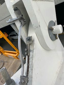
- The causes of the LED lighting problems were multilayered, interrelated, and involved all three parts of a PQ problem — the quality of the voltage delivered to the LED drivers, the performance of the infrastructure’s wiring and grounding system, and the PQ immunity of the LED drivers. More specifically, it was the voltage quality at the AC input of the drivers, insufficient surge protection on the lighting control system, problems within the wiring and grounding of the new AC infrastructure on the canopies and existing AC power infrastructure just inside the terminal, the installation quality and grounding of the lightning protection system (LPS) installed on the canopies (Photo 2), and a “hole” in the susceptibility of the AC input network of the driver design. These five causes worked together to raise the risk of LED lighting problems high enough to cause noticeable LED problems and driver failures.
What misconceptions did the customer have?
The challenges arising from any PQ investigation invite typical and unique PQ misconceptions. This problem, however, presented a combination of myths that required careful thought. Here are several PQ misconceptions that had to be debunked, resolved, and explained to the customer.
Myth #1: Despite high reliability and quality power meeting industry standards, incoming electric utility power may cause LED lighting problems.
Fact #1: From PQ monitoring, the electric utility power source was ruled out as causing or contributing to the LED lighting problems.
Myth #2: Sizing surge protective devices (SPDs) internal to electronic loads according to standard industry guidelines will help reduce the risk of premature SPD failure (thus product failure) even when an SPD is applied after an EMI filter.
Fact #2: If sized correctly, the SPD after the EMI filter in the LED drivers can withstand the energy (heat) when a surge occurs. However, the common everyday disturbance (oscillatory wave occurring at the peak) from the normal operation of electrical and electronic loads (e.g., escalator VFDs) in the airport terminal was amplified by the driver’s internal EMI filter, which exposed the SPD on the output of the filter to undergo additional heating, leading to its premature failure. Failure of the SPD caused the driver’s AC line fuse to blow.
Myth #3: Application of SPDs along low-voltage control circuits and control system components isn’t needed because control circuits are not power circuits, and the control voltage is low.
Fact #3: Application of properly sized and located SPDs on control circuits is critical to the preservation of the signal and the protection of the control system components to avoid causing internal damage to the driver and proper driver control functions.
Myth #4: Grounding of the canopies and LED luminaires installed on the canopies had nothing to do with the malfunctions and failures of the LED lighting system. (Grounding of structures, electrical systems, and electronic loads don’t do anything — so it’s not important. Therefore, questioning it shouldn’t be included in a PQ investigation.)
Fact #4: Grounding of the LED luminaires, the driver, and the canopy structure played a key role in the malfunctions and failures of the LED lighting system. (Properly grounding of metal infrastructures supporting LED lighting, lighting fixtures, and the drivers within helps stabilize (keep close to 0V) the whole grounding system, especially when voltage surges impact AC power circuits and control circuits.)
Myth #5: New LPS installations on large outdoor metal structures (interfaced with existing LPS-protected buildings) that must support programmable LED lighting will perform the same as LPSs installed on large building structures that must support programmable LED lighting.
Fact #5: Careful installation and evaluation of the bonding of the components of the metal structure and the bonding of LPS connector hardware and its down conductors must be carried out to ensure the LPS system operates under low impedance conditions to help ensure adequate protection and performance of electronic loads like LED lighting. This type of installation is not the same as what you find on a typical building structure.
Myth #6: The malfunctions and failures of the LED lighting equipment (drivers and control system components) were associated with one simple cause.
Fact #6: Most PQ-related problems with electronic loads, especially controllable loads like most LED lighting, involve more than one cause and are complex.
Myth #7: Thunderstorms passing over large metal structures that must support electronic equipment are typically the single disturbance cause of PQ-related equipment problems.
Fact #7: Since the canopies were constructed from large steel beams exposed to the outdoors, lightning from passing thunderstorms was not the only contributing cause to the malfunctions and failures of the LED lighting system. The oscillatory disturbance caused by the power electronics inside the VFDs controlling the elevator motors was the second disturbance cause that impacted the LED drivers.
What common culprits were found?
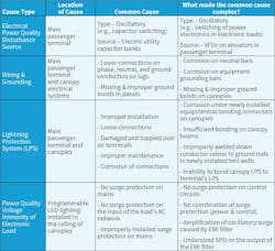
Table 2 lists the common and uncommon causes found inside the airport terminal and on the canopies. In the terminal, the electronic loads (e.g., VFDs) were acting as the source of the disturbances, and its electrical system couldn’t provide a stable neutral and ground system. On the canopies, the voltage immunity of electronic loads (e.g., LED drivers) allowed the oscillatory surges from the operation of the VFDs on the elevators to damage the metal oxide varistor (MOV) downstream of the EMI filter (the MOV on the input of the EMI filter was not damaged). The grounding problems found on the canopy’s electrical system and its LPS compromised the voltage reference for the canopy-mounted controls as well as the LED drivers.
What disturbances made the problem more difficult to investigate?
Voltage sags did occur on the electric utility power source but posed no problems to the operation of the canopy’s LED lighting and other electrical systems. One added challenge to this investigation was the identification of the oscillatory surge waves (occurring at the voltage peak) generated by the operation of the VFDs on the elevators that operated 24 hours per day.
A second more complex challenge was explaining why the EMI filter inside the LED driver amplified the oscillatory wave increasing its threat to the second MOV. Normally, the magnitude of these waves poses no problem to electronic loads if proper surge protection is designed in. However, because the EMI filter in the LED driver amplified the waves, the SPD on the output of the filter experienced too much heating.
How and why did normal electric utility system operations make this problem difficult to investigate?
Because voltage sags were found to occur on the circuit powering the canopies, some end-users were concerned that the sags were causing the LED lighting malfunctions and failures. The fact that this circuit was a network underground circuit also made the investigation challenging, since fewer disturbances occur on these circuits.
Scenario #2. Uncommon PQ Culprits Cause Long-Term Interruptions at Large Parcel Sorting Facility
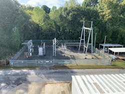
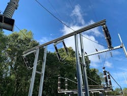
A large parcel sorting facility is powered by an on-site 115kV to 12.47kV customer substation feeding a double-ended 12.47kV switchgear system powering one 12.47kV to 4.16kV transformer (Photo 3). Four downstream switchgear systems with 4.16kV to 480V step-down transformers fed 480V power distribution systems powering a plethora of non-linear electronic loads (e.g., VFDs, PLC, power supplies, electronic lighting, etc.). Four soft-start chillers (three large and one small) are powered by the 4.16kV bus. The facility uses a large number of VFDs (1 to 250 hp) to move parcels 24 hours a day.
The facility experienced some long-term power interruptions. Each interruption created two to three hours of downtime not including time to restart each machine. Moreover, the plant often experienced problems with restarting sorting systems after an interruption. Plant downtime caused delays in sorting parcels and reloading outgoing trucks, which caused late deliveries of packages to customers and delays in receiving new parcels from incoming trucks. The PQ problems caused significant time delays and financial burdens, especially during special family days (e.g., Mother’s Day) and during the holidays.
What made this case unique?
Investigating PQ problems involving the long-term interruption of power to an industrial facility is not typically challenging. However, multiple causes working together to cause the interruptions and the large number of end-use equipment problems at this facility/the time it took to identify and fix all of them proved to be quite challenging. Here’s a list of the problems that were identified.
- 115kV primary side electric utility transmission system fuses (Photo 4) at the customer’s substation blew eight times in one calendar year with the first event during the early morning hours of January 1st. These events occurred during all seasons, on various days of the week, and at random times of the day.
- The footprint of the industrial facility was large and used a large number of vintage VFDs ranging from 1 to 250 hp. (VFDs can be linked to a wide variety of PQ problems and should always be considered as a potential culprit.)
- The causes of the 115kV fuses blowing were multilayered and involved all three parts of a PQ problem — the electric utility source (5MVA transformer stepping 115kV down to 4.16kV), the power distribution system inside the facility, and the characteristics of the non-linear electronic loads (i.e., VFDs).
- There was no pattern to the interruptions regarding the primary phase, month, day, or time of day.
- The 5MVA utility-owned transformer was only half-loaded but was original to the site.
- The first fuse-blowing event (January 1st) revealed a failure of the terminations where the bare electric utility substation conductors to insulated medium-voltage (MV) cable going underground to the customer’s 12.47kV switchgear were joined.
What misconceptions did the customer have?
The challenges arising from any PQ investigation invite typical misconceptions. This problem, however, presented a combination of misconceptions that required careful thought during the investigation. Following is a list of PQ misconceptions present in this case.
Myth #1: Failures of primary side fuses upstream of a normally loaded transformer (i.e., under the unit’s rating) are never related to the customer’s load, especially when the substation transformer is half-loaded.
Fact #1: Always consider the static and dynamic PQ characteristics of the customer’s load when investigating any fuse failures. Fuses use fuse links that have specific time-current characteristics that represent the current squared (I2) and the time (t) it takes for the fuse to melt (i.e., increase the link’s temperature). Words missing? he melting point) are ratings that help ensure the heat caused by all currents flowing through a link has enough time to flow away from the fuse to its connected circuitry. Expected fault currents (occurring less frequently) and their duration and inrush currents (occurring more frequently from the starting of large loads) and their duration are examples of dynamic PQ characteristics. For example, 60-Hertz steady-state currents are static PQ characteristics. Fuses with higher I2t values can handle larger current surges for longer durations before blowing. However, harmonic currents, which typically range from 120Hz to 3kHz, cause fuse link heating, are also steady-state currents that are static PQ characteristics drawn by electronic loads and are not included when testing fuses to industry standards. The true RMS current that fuses will respond to includes the static and dynamic current characteristics.
Myth #2: Failures of MV terminations (electric utility side to customer’s MV cable) exhibiting heating at the joint are always related to termination characteristics (e.g., high resistance developing over time) and exposure to its surrounding environment (the substation was in use for over 20 years).
Fact #2: Other PQ-related causes related to the electric utility source, customer’s power distribution system, and electronic loads can lead to termination failures.
Myth #3: The blowing of any electric utility primary side fuse is caused by one single PQ phenomenon.
Fact #3: Fuses will respond to multiple types of PQ phenomena: voltage or current imbalance, overloading, inrush current, load profile (i.e., how often the load is stopped and started), harmonics, and temperature.
Myth #4: Blowing of electric utility side fuses is always caused by an electric utility PQ problem. In PQ, poor voltage PQ can impact the customer’s electrical system and its loads. Poor current PQ originating inside the customer’s facility can impact the customer’s electrical system and the voltage PQ. Hence, the two are very interrelated.
Fact #4: Always rely on this piece of advice from PQ experts: “The voltage belongs to the utility, and the current belongs to the customer.” With this, both voltage PQ and current PQ should always be considered when investigating any PQ problem.
Myth #5: Electric utility primary side fuse failures are only caused by the 60 Hertz-related characteristics of the load.
Fact #5: While fuses will respond to any current (within a reasonable frequency range) flowing through them, the characteristics of the whole total current (the true RMS current) must be considered, not just the 60-Hertz components.
What common culprits were found?
A growing number of PQ-related equipment problems have both simple and complex causes that often occur simultaneously and work together to increase the risk of malfunctions and failures and cause trouble presenting unusual challenges to the PQ investigator. Addressing what might seem to be a single cause is typically not enough to properly address the problem. What common and uncommon causes were found?
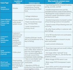
Table 3 lists the common and uncommon causes of the 115kV primary side fuse blowing found in the customer’s parcel sorting facility.
Each of the eight instances of primary side fuse blowing was caused by customer-related PQ problems. However, no single cause was deemed the culprit that caused any of the fuse-blowing events. The three primary causes of the fuse failures that worked together to cause the fuse-blowing events were:
- Outside temperatures: On days when the outside temperature was above 90°F, more 115kV fuse-blowing events occurred.
- Harmonics from VFDs: Significant harmonics (5th, 7th, and 11th) from the VFDs were flowing to the VFDs through the customer’s power distribution system at all times, passed through the 5MVA electric utility power transformer, and flowed through the 115kV fuses. However, during heavy parcel sorting seasons (family days and holidays), the harmonics from the VFDs as well as the total harmonic current were higher. The investigation determined that the magnitude of these harmonics also increased fuse loading, which further caused unknown derating of the fuse. The interesting part here is that fuses are not tested under harmonic conditions (according to industry standards) to determine which type (harmonic number) and how much harmonics affect their performance.
- Malfunction of chiller: The only operational chiller, which kept the facility cool, had an undetected problem — it had a malfunctioning water line flow switch which caused the chiller to stop and restart frequently (i.e., 10 to 15 times per hour). This frequent restarting caused high inrush currents to occur too close together in time. This also caused an increase in the 115kV fuse temperature.
No single cause was the primary cause of the fuse-blowing events. The combined effects of the three primary causes and how they were interrelated to each other made this PQ investigation very challenging. In addition, the 5MVA transformer that exhibited no problems and was only half-loaded also presented challenges as dissolved gas analysis (DGA) testing indicated no problems.
What disturbances and other conditions made the problem more difficult to investigate?
Interestingly, the sorting facility had no previous history of interruptions caused by fuse blowing, which indicated something regarding one or more of the loads likely changed in the months before the first fuse-blowing event that occurred on January 1st. Voltage sags detected by temporary PQ monitoring inside the facility did occur on the electric utility power source but blew no fuses and posed no problems to the operation of the facility. In addition, no harmonic voltage problems or voltage imbalances were found on the 115kV source feeding the 5MVA transformer. Moreover, the use of infrared thermography found no loose hardware or defective fuse holders on any of the fuses.
One condition that continuously kept the minds of the PQ investigators thinking was the half-loaded 5MVA transformer. Another fuse metric that would have been useful to measure but could not be measured is the “walking wounded damage” that occurred within the fuse links due to the effects of the temperature, harmonics, and frequent inrush currents. Blown fuse links were removed and examined to determine if any other clues could be found that would have helped the PQ investigators.
Lessons learned
One can see that these two PQ scenarios involved more than one cause. Moreover, the PQ investigators had to list out all of the common and uncommon causes of MV fuses blowing and then try to rationalize each one. Temporary PQ monitoring at the revenue meter did reveal some useful data. However, careful analysis of this data had to take place, so the investigators could relate specific parts of the data to the operation of specific loads such as the chillers and VFDs.
The increasing complexity of electrical systems inside customer facilities and the growing number and complexity of electronic loads powered by them are two important contributing factors that make PQ investigations more difficult to carry out. In addition, the increasing complexity of the electric utility grid as utilities entertain the interconnection of DG technologies to transmission and distribution systems will continue to increase the complexity of PQ investigations. PQ training — whether basic, intermediate, or advanced — will certainly help electrical professionals interested in this type of work learn more about how to navigate an investigation. Moreover, increased field experience in investigating electric utility and customer PQ problems is also one of the best approaches to learning more about how to conduct effective investigations.
PBE Engineers, LLC, provides power quality products and services based on decades of experience serving PQ monitor manufacturers and utility, commercial, and industrial markets. They can be reached at [email protected].

