During a power quality inspection to evaluate the integrity of a critical communication uninterruptible power supply (UPS) system, a discovery was made in one of the 125A panelboards. After evaluating the UPS installation, we proceeded to inspect all the downstream panelboards. At one of the downstream panelboards, a red placard had been placed on the door (Photo 1). It read, “SPECIAL GROUNDING – DO NOT CHANGE.” We had never seen a sign like this, so it piqued our curiosity to say the least. It also made us proceed with great caution.
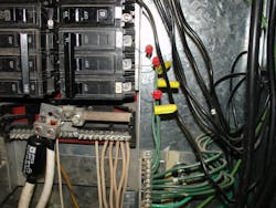
The National Electrical Code (NEC) doesn’t have a section for “Special Grounding,” nor would most electricians ever use this phrase. Before opening this panel to inspect it, we put on our 40 cal/cm2 arc flash suits. One person carefully removed the cover while another trained his eyes on what lay behind the cover as it was slowly removed. Once the cover had been removed, we were stunned with what we found. Can you identify the safety issue in the Photo 2? What were the installers trying to accomplish?
In the photo, three red components are connected between a 15A 3-pole circuit breaker and the ground bus. Notice the circuit breaker is in the “ON” position. Without further explanation of the devices, there are glaring safety issues. An unknowing electrician could be shocked by the bare wires or create an arc flash by accidentally pushing the devices together. This is a dangerous trap!
What is this device the installer created? It’s a homemade non-UL-listed surge protective device (SPD). The red components are metal oxide varistors (MOVs). MOVs are designed to prohibit voltage conduction at nominal voltage. When the break-through voltage is reached during a transient overvoltage, the MOV changes from an insulator and begins to conduct, thus providing a low impedance path to the grounding system for surge current to flow.
There are several problems with this installation. Besides the shock and arc flash hazard, the installer was attempting to protect the panel and load from transient voltage. The first problem is the Joule (energy) rating of these MOVs. They’re likely not high enough to be effective at a panelboard. A transient at this level of the electrical system will be high enough to cause critical failure — possibly enough to start an arc flash event resulting in critical failure. Perhaps more importantly, this panelboard was downstream of a UPS that already had an SPD installed on the front end and was actively regenerating the voltage output void of power quality anomalies. An SPD is not necessary for this installation and was identified as a safety and reliability flaw.
Unfortunately, after providing the customer with these findings, they refused to remove the hazard. Please be extremely careful if you ever run across a “SPECIAL GROUNDING” sign.
About the Author
Bryan Glenn
Power Quality Consultant
Bryan Glenn is a power quality consultant for EC&M magazine. He can be reached at [email protected].


