All questions and answers are based on the 2011 NEC.
Q. What are the requirements for the location of the service disconnecting means?
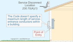
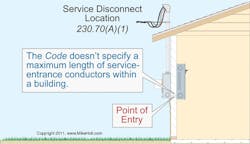
A. The service disconnecting means must be placed at a readily accessible location either outside the building/structure, or inside nearest the point of service conductor entry [230.70(A)(1)] (Figure).
Warning: Because service-entrance conductors don’t have short circuit or ground fault protection, they must be limited in length when installed inside a building. Some local jurisdictions have a specific requirement as to the maximum length permitted within a building.
The service disconnecting means isn’t permitted to be installed in a bathroom [230.70(A)(2)]. In addition, overcurrent devices must not be located in the bathrooms of dwelling units, or guest rooms/guest suites of hotels or motels [240.24(E)].
If a remote-control device (such as a push button for a shunt-trip breaker) is used to actuate the service disconnecting means, then the service disconnecting means must still be at a readily accessible location either outside the building/structure or nearest the point of entry of the service conductors as required by 230.70(A)(1) [230.70(A)(3)]. See the definition of “Remote Control” in Art. 100. The service disconnecting means must consist of a manually operated switch, a power-operated switch, or a circuit breaker that’s also capable of being operated manually [230.76].
Each service disconnecting means must be permanently marked to identify it as part of the service disconnecting means [230.70(B)]. When a building/structure has multiple services and/or feeders, a plaque is required at each service or feeder disconnect location to show the location of the other service or feeder disconnect locations. [See Sec. 230.2(E).] Each service disconnecting means must be suitable for the prevailing conditions [230.70(C)].
Q. When is a common neutral counted as a current carrying conductor in a conduit for calculating conductor ampacity?
A. According to 310.15(B)(5), the following rules determine when a neutral is considered current carrying for purposes of applying the adjustment factors of 310.15(B)(2)(a):
(a) The neutral conductor of a 3-wire, single-phase, 120/240V system, or 4-wire, 3-phase, 120/208V or 277/480V wye-connected system, isn’t considered a current-carrying conductor for conductor ampacity adjustment of 310.15(B)(3)(a) [310.15(B)(5)(a)].
(b) The neutral conductor of a 3-wire circuit from a 4-wire, 3-phase, 120/208V or 277/480V wye-connected system is considered a current-carrying conductor for conductor ampacity adjustment of 310.15(B)(3)(a) [310.15(B)(5)(b)]. Note: When a 3-wire circuit is supplied from a 4-wire, 3-phase, 120/208V or 277/480V wye-connected system, the neutral conductor carries approximately the same current as the ungrounded conductors.
(c) The neutral conductor of a 4-wire, 3-phase, 120/208V or 277/480V wye-connected system is considered a current-carrying conductor for conductor ampacity adjustment of 310.15(B)(3)(a) if more than 50% of the neutral load consists of nonlinear loads [310.15(B)(5)(c)]. Note: Nonlinear loads supplied by a 4-wire, 3-phase, 120/208V or 277/480V wye-connected system can produce unwanted and potentially hazardous odd triplen harmonic currents (3rd, 9th, 15th, and so on) that can add on the neutral conductor. To prevent fire or equipment damage from excessive harmonic neutral current, the designer should consider increasing the size of the neutral conductor or installing a separate neutral for each phase. For more information, see 210.4(A) Note, 220.61 Note 2, and 450.3 Note 2.
About the Author

Mike Holt
Mike Holt is the owner of Mike Holt Enterprises (www.MikeHolt.com), one of the largest electrical publishers in the United States. He earned a master's degree in the Business Administration Program (MBA) from the University of Miami. He earned his reputation as a National Electrical Code (NEC) expert by working his way up through the electrical trade. Formally a construction editor for two different trade publications, Mike started his career as an apprentice electrician and eventually became a master electrician, an electrical inspector, a contractor, and an educator. Mike has taught more than 1,000 classes on 30 different electrical-related subjects — ranging from alarm installations to exam preparation and voltage drop calculations. He continues to produce seminars, videos, books, and online training for the trade as well as contribute monthly Code content to EC&M magazine.

