Part II of Art. 690 provides the circuit requirements for PV systems. The first requirement it covers is the maximum PV system direct-current (DC) circuit voltage. This value is used when selecting conductors, cables, and equipment, determining working space, and other applications where circuit voltage ratings are used. The maximum PV system DC circuit voltage is the highest voltage between any two conductors of a circuit. It must comply with Sec. 690.7(1), (2), and (3). Essentially, this value is limited to 1,000V for multifamily, commercial, and industrial buildings, and limited to 600V for one- and two-family residential buildings. Where it exceeds 1,000V, the system must be installed per Sec. 690.31(G).
You determine this voltage by one of three methods:
- Manufacturer’s Instructions. The PV system DC source circuit voltage equals the sum of the series-connected DC modules’ open-circuit voltage (Voc) in a PV string circuit as corrected for the lowest expected ambient temperature using the manufacturer’s voltage temperature coefficient correction [Sec. 690.7(A)(1)].
- Table of Crystalline and Multicrystalline Modules. The PV system DC source circuit voltage equals the sum of the series-connected DC modules’ rated open-circuit voltage (Voc) in a PV string circuit as corrected for the lowest expected ambient temperature per Table 690.7(A).
- Engineered Industry Standard Method. For PV systems with an inverter generating capacity of 100kW or greater, the PV system DC circuit voltage can be determined by a licensed professional electrical engineer who provides a documented and stamped PV system design using an industry standard method for maximum DC voltage calculation.
You must also calculate the DC-to-DC converter circuit voltage based on the manufacturer’s instructions [Sec. 690.7(B)(1) or (B)(2)]:
- For a single DC-to-DC converter, it’s equal to the rated output DC voltage of the converter (optimizer).
- For series-connected DC-to-DC converters, it’s equal to the sum of the rated output voltage of the converters.
Circuit current and conductor sizing
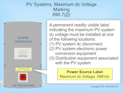
Install a permanent, readily visible label indicating this voltage at one of these locations [Sec. 690.7(D)], as shown in Fig. 1:
(1) PV system DC disconnect
(2) PV system electronic power converters
(3) Distribution equipment associated with the PV system
If the PV system is rated below 100kW, the maximum PV system circuit current is 125% of the sum of the short-circuit current ratings of the PV modules connected in parallel [Sec. 690.8(A)(1)(a)(1)].
If it’s rated 100kW or more, the requirements are considerably greater [Sec. 690.8(A)(1)(a)(2)]. Among other things, it must be based on the highest three-hour current average resulting from the simulated local irradiance on the array accounting for elevation and orientation. In no case is the PV source circuit DC current permitted to be less than 70% of the PV source circuit DC current as calculated in Sec. 690.8(A)(1)(a)(1).
Where a circuit is protected with an overcurrent protective device (OCPD) not exceeding the conductor ampacity, the maximum current is permitted to be the rated input current of the inverter to which it is connected [Sec. 690.8(A)(2)].
PV circuit conductors must have an ampacity of at least the largest of Sec. 690.8(B)(1) or (B)(2):
(1) Conductor Sizing. PV circuit conductors must have an ampacity of at least 125% of the current as determined by Sec. 690.8(A).
Exception: Where the assembly, including the OCPDs protecting the circuit(s), is listed for operation at 100% of its rating, the ampere rating of the OCPD can be sized to 100% of the continuous and noncontinuous loads.
(2) Conductor Sizing, With Ampacity Correction and/or Adjustment. PV circuit conductors must have an ampacity of at least 100% of the current as determined by Sec. 690.8(A) after conductor ampacity correction [Table 310.15(B)(1)(1)] and adjustment [Table 310.15(C)(1)].
Where overcurrent is provided for parallel-connected PV string circuits, the conductor ampacity must be at least [Sec. 690.8(D)]:
(1) The rating of the overcurrent device.
(2) The sum of the currents as calculated in Sec. 690.8(A)(1)(a) for the other parallel-connected PV string circuits protected by an overcurrent device.
Overcurrent protection
PV system DC circuit and inverter output conductors and equipment must be protected against overcurrent [Sec. 690.9(A)]. But OCPDs are not required where these two conditions are met [Sec. 690.9(A)(1)]:
(1) The PV system DC circuit conductors have an ampacity of at least the DC current per Sec. 690.8(B).
(2) Where the currents from all PV sources do not exceed the OCPD rating specified by the manufacturer for the PV module or electronic power converters (inverters and DC-to-DC converters).
OCPDs are required for PV system circuit conductors connected at one end to a current-limited supply and also connected to sources having an available circuit current greater than the ampacity of the conductor at the point of connection to the higher current source [Sec. 690.9(A)(2)].
PV circuit conductors that do not comply with Sec. 690.9(A)(1) or
(A)(2) must have overcurrent protection by one of the four methods described in Sec. 690.9(A)(3)(1) through (4). For example, PV circuit conductors that are not in a building and are not longer than 10 ft must have overcurrent protection at one end of the circuit.
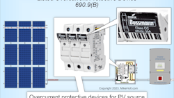
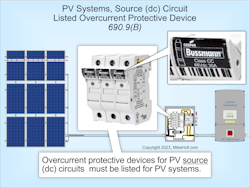
OCPDs for PV source (DC) circuits must be listed for PV systems [Sec. 690.9(B)], as shown in Fig. 2.
Electronic devices that are listed to prevent backfeed in PV DC circuits are permitted to prevent overcurrent of conductors on the PV array side of the electronic device.
OCPDs required by Sec. 690.9(A)(2) must comply with one of the following (the next higher standard size OCPD per Sec. 240.4(B) is permitted).
(1) OCPDs for PV circuits must have an ampere rating of at least 125% of the currents as calculated in Sec. 690.8(A).
(2) Where the assembly — together with its OCPD(s) — is listed for continuous operation at 100% of its rating, the OCPD can be sized at 100% of the currents as calculated in Sec. 690.8(A).
A single OCPD on one of the two circuit conductors can be used to protect PV modules and DC-to-DC converter circuit conductors [Sec. 690.9(C)]. Where a single OCPD is used, it must be placed in the same polarity for all circuits within the PV system.
PV system DC circuits, on or in a building, operating at 80VDC or greater must be protected by a listed PV arc-fault circuit interrupter or other component listed to provide equivalent protection [Sec. 690.11].
Arc fault protection is not required for PV system DC circuits in metal raceways, metal-clad cables, enclosed metal cable trays, or underground if they meet either exception condition in Sec. 690.11.
Rapid shutdown
The rapid shutdown function reduces the risk of electrical shock to firefighters. The AC output conductors from PV systems will be either de-energized after shutdown initiation or remain energized if supplied by other sources of power. To prevent PV systems with AC output conductors from remaining energized, they must be controlled by the rapid shutdown function after shutdown initiation.
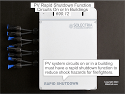
PV system circuits on or in a building must have a rapid shutdown function per Sec. 690.12(A) through (D), as shown in Fig. 3.
A rapid shutdown system will use three strategies: controlled conductors [Sec. 690.12(A)], controlled limits [Sec. 690.12(B)], and initiation device [Sec. 690.12(C)]. The requirements for these can be a bit complex. For example, if you have controlled limits, there is one requirement for outside the array boundary and another for inside the array boundary. If inside the array boundary, you can choose between two requirements [Sec. 690.12(B)(1) and (2)]. Here’s one of them: “The PV system provides shock hazard control for firefighters by using a PV hazard control system installed per the manufacturer’s instructions. Where a PV hazard control system requires initiation to transition to a controlled state, the rapid shutdown initiation device [Sec. 690.12(C)] must perform this initiation.”
Two exceptions to the mandatory rapid shutdown function exist:
Exception No. 1: A rapid shutdown function is not required for ground-mounted PV system conductors that enter buildings whose sole purpose is to house PV system equipment.
Exception No. 2: PV equipment and circuits installed on nonenclosed detached structures including, but not limited to, parking shade structures, carports, solar trellises, and similar structures, are not required to comply with the rapid shutdown requirements of Sec. 690.12.
A building with a rapid shutdown function must have a permanent label indicating the location of all rapid shutdown initiation devices. It must be near the service equipment or at an approved readily visible location [Sec. 690.12(D)] and meet the specifications of Sec. 690.12.
Don’t miss the details
You may be thinking the circuit requirements for PV systems are not all that different than the ones for other applications. You just have to determine the DC system voltage on the front end and add a rapid shutdown on the back end. That’s not a bad way to sum it up. Just don’t miss all of the details in those two add-on tasks.
About the Author

Mike Holt
Mike Holt is the owner of Mike Holt Enterprises (www.MikeHolt.com), one of the largest electrical publishers in the United States. He earned a master's degree in the Business Administration Program (MBA) from the University of Miami. He earned his reputation as a National Electrical Code (NEC) expert by working his way up through the electrical trade. Formally a construction editor for two different trade publications, Mike started his career as an apprentice electrician and eventually became a master electrician, an electrical inspector, a contractor, and an educator. Mike has taught more than 1,000 classes on 30 different electrical-related subjects — ranging from alarm installations to exam preparation and voltage drop calculations. He continues to produce seminars, videos, books, and online training for the trade as well as contribute monthly Code content to EC&M magazine.