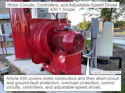
Article 430 contains the specific rules for conductor sizing, overcurrent protection, control circuit conductors, controllers,, and disconnects for electric motors. The installation requirements for air-conditioning and refrigeration equipment are in Art. 440; those supplement or amend Art. 430 requirements.
Article 430 is long and complex because motors are complex. They are inductive loads with a high-current demand at start-up (typically six or more times the running current). This makes overcurrent protection for motor applications necessarily different from the overcurrent protection for other types of equipment. So, do not confuse general overcurrent protection with motor protection — you must calculate and apply them differently using the rules in Art. 430 (Fig. 1).
Table FLC versus motor nameplate current rating
The size of conductors supplying equipment covered by Art. 430 must be selected from the ampacity tables per Sec. 310.15 or be calculated per Sec. 310.14(B) [Sec. 430.6].
Determine motor current ratings using:
- Section 430.6(A)(1) Table Full-Load Current (FLC). Use the motor full-load current ratings in Tables 430.247 through 430.250 to determine conductor sizing [Sec. 430.22] and the branch-circuit short-circuit and ground-fault overcurrent protection size [Sec. 430.52 and 430.62].
- Section 430.6(A)(2) Motor Name-plate Current Rating (FLA). Overload devices and conductor sizing for other than continuous-duty motors must be sized based on the motor nameplate full-load ampere (FLA) rating per Sec. 430.31.
Motor locations
Locate motors so they have adequate ventilation and can readily be maintained [Sec. 430.14(A)]. Locate open motors with commutators or collection rings so they don’t spew sparks onto combustible material [Sec. 430.14(B)
Highest rated motor
You determine the highest rated motor of a group when you need to calculate conductor size and the short-circuit ground-fault protective device/the conductors are supplying more than one motor [Sec. 430.24]. The highest rated motor of the group is the one with the largest full-load current (FLC) rating as listed in Tables 430.247 through 430.250 [Sec. 430.17].
Motor conductor size
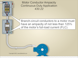
Branch-circuit conductors to a single motor in a continuous-duty application must have an ampacity of at least 125% of the motor’s FLC as listed in Tables 430.247 through 250 [Sec. 430.6(A)(1) and Sec. 430.22(A) through (G)], as shown in Fig 2.
Conductors that supply several motors must be sized to at least the sum of the four quantities enumerated in Sec. 430.24 (1) through (4). These are:
(1) 125% of the highest rated motor’s FLC as listed in Tables 430.247 through 250.
(2) The sum of the FLC of the other motors as listed in Tables 430.247 through 250.
(3) 100% of the noncontinuous non-motor load.
(4) 125% of the continuous non-motor load.
The last sentence above each table allows us to use the ampacity columns for a range of system voltages without any adjustment. The conductor size must be selected from Table 310.16 per the terminal temperature rating (60°C or 75°C) of the equipment [Sec. 110.14(C)(1)]. Don’t use the motor nameplate full-load amperes (FLA) [Sec. 430.6(A)(2)] to determine the motor conductor size.
Motor applications are considered continuous duty unless the nature of the control or apparatus the motor drives is designed so the motor will not operate continuously under load [Table 430.22(E) Note]. When a motor is not continuous duty because of this type of application, size the conductors using the percentages of Table 430.22(E). If a motor must stop when performing its function (such as in the case of an elevator motor), it is a good sign the motor is intermittent duty.
Conductors for a motor used in a short-time, intermittent, periodic, or varying-duty application must have an ampacity of at least the percentage of the motor nameplate FLA rating shown in Table 430.22(E).
Overload
equipment operates above its current rating,or where the current exceeds the conductor ampacity. When an overload condition persists, equipment failure or fire from damaging or dangerous overheating can result. A fault, such as a short circuit or ground fault, is not an overload [Art. 100].
Overload devices protect motors, motor control equipment, and motor branch-circuit conductors against excessive heating due to motor overloads and failure to start — but not against short circuits or ground faults. Overload protection is not required where it might introduce additional or increased hazards, as in the case of fire pumps [Sec. 430.31(A)].
Overload devices can be:
- Thermal overloads (heaters) in an overload relay of a motor contactor (starter). These heater units are selected using a chart or size given by the manufacturer.
- Solid-state (electronic) overloads have an adjustment dial for setting the trip level. They are installed in an overload relay of a motor contactor (starter).
- Inverse time circuit breakers and dual element fuses can serve as both motor overload protection and the motor short-circuit ground-fault protection if the requirements of Sec. 430.32 are met [Sec. 430.55].
- Fuses, when sized per Sec. 430.32(A) [Sec. 430.36].
Overload sizing for continuous-duty motors
Motors rated more than 1 hp (used in a continuous-duty application without integral thermal protection) must have the overload device(s) sized per one of the four methods required in Sec. 430.32(A)(1) through (4).
For example, you can use a separate overload device. This device must be selected to open at no more than 125% of the motor nameplate FLA rating depending on service factor or temperature rise:
- Service Factor (SF). Motors with a marked service factor of 1.15 or more on the nameplate must have the overload device sized at not more than 125% of the motor nameplate current rating. Motor service factors are safety factors; they indicate how much the motor capacity can be exceeded for short periods without overheating. For example, a motor with a service factor of 1.15 can operate at 15% more than its rated output without overheating. This is important for motors where loads vary and may peak slightly above the rated torque.
- Temperature Rise. Motors with a nameplate temperature rise of 40°C or less must have the overload device sized no more than 125% of the motor nameplate current rating. A motor with a nameplate temperature rise of 40°C means the motor is designed to operate so it will not heat up more than 40°C above its rated ambient temperature when operated at its rated load and voltage. Studies have shown that when the operating temperature of a motor is increased 10°C above its rating, the motor winding insulating material’s anticipated life is reduced by 50%.
Example
Question: A motor has a nameplate that specifies a service factor of 1.12 with a temperature rise of 41°C and a nameplate full load current rating of 25A. What size dual-element time-delay fuse is required for the overload protection of this motor?
Solution: Since the service factor of 1.12 is less than 1.15, and 41°C is over 40°C, the overload protection is sized based on 115 percent of the motor nameplate ampere rating [Sec. 430.6(A)(2)].
Overload Protection = 25A × 115%
Overload Protection = 28.75A
Answer: Therefore, use a 25A dual-element time-delay fuse [Sec. 240.6(A)]
Other Motors. No more than 115% of the motor “nameplate current rating.”
Branch-circuit short-circuit and ground-fault protection
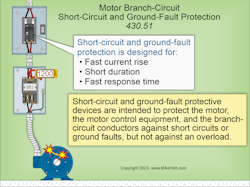
A branch-circuit short-circuit and ground-fault protective device (OCPD) protects the motor, the motor control equipment, and the conductors against short circuits or ground faults, but not against overload [Sec. 430.51] (Fig. 3).
We’ll get into the details in Part 2 of this article.
Fundamentally different
It should be clear at this point that conductor protection for motors is fundamentally different from conductor protection in other applications. Why is this?
When voltage is first applied to the field winding of an induction motor, only the conductor resistance opposes the flow of current through the motor winding. Because the conductor resistance is so low (practically a dead short), the motor will momentarily have a large inrush current.
Once the rotor reaches its rated speed, the starting current reduces to running current due to counter-electromotive force (CEMF).
If the rotating part of the motor winding (armature) becomes jammed so it cannot rotate, no CEMF will be produced in the motor winding. This results in a decrease in conductor impedance to the point that it is effectively a short circuit. The motor then operates at locked-rotor current (often six times the full-load ampere rating), depending on the motor’s Code letter rating [Sec. 430.7(B)]. This condition will cause the motor winding to overheat and be destroyed if the current is not quickly reduced or removed.
These materials are provided by Mike Holt Enterprises in Leesburg, Fla. To view Code training materials offered by this company, visit www.mikeholt.com/code.
About the Author

Mike Holt
Mike Holt is the owner of Mike Holt Enterprises (www.MikeHolt.com), one of the largest electrical publishers in the United States. He earned a master's degree in the Business Administration Program (MBA) from the University of Miami. He earned his reputation as a National Electrical Code (NEC) expert by working his way up through the electrical trade. Formally a construction editor for two different trade publications, Mike started his career as an apprentice electrician and eventually became a master electrician, an electrical inspector, a contractor, and an educator. Mike has taught more than 1,000 classes on 30 different electrical-related subjects — ranging from alarm installations to exam preparation and voltage drop calculations. He continues to produce seminars, videos, books, and online training for the trade as well as contribute monthly Code content to EC&M magazine.


