The Differences Between Grounding and Bonding — Part 2 of 12
This article is the second in a 12-part series on the differences between grounding and bonding.
What is a separately derived system (SDS)? Its defining characteristic is that it’s not connected to the current-carrying conductors of another electrical source. The NEC defines it as an electrical source (other than a service) that has no direct connection to circuit conductors of any other electrical source other than those established by grounding and bonding connections [Art. 100]. A power transformer or an onsite generator may be installed as an SDS.
SDS grounding
You must run a grounding electrode conductor (GEC) to one or more grounding electrodes per Sec. 250.50 and Sec. 250.30(C) from the same location where the system bonding jumper has been installed [Sec. 250.30(A)(4)]. Size it per Sec. 250.66, based on the area of the largest secondary phase conductor [Sec. 250.30(A)(5)].
If the SDS is indoors, you must install the required system bonding jumper at the secondary neutral terminal of the SDS or at the first system disconnect [Sec. 250.30(A)(1)(a)] and size it per Table 250.102(C)(1), based on the area of the secondary phase conductor.
SDS supply-side bonding jumper
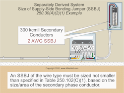
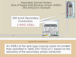
You must run a supply-side bonding jumper from the SDS equipment grounding conductor terminal to the equipment grounding conductor terminal on the secondary system disconnect enclosure and size it per Table 250.102(C)(1), based on the area of the secondary phase conductor [250.30(A)(1)].
Example question: What size supply-side bonding jumper is required for flexible metal conduit containing 300kcmil secondary conductors (Fig. 1)?
Answer: 2 AWG, based on the 300kcmil conductors [Table 250.102(C)(1)]
When the system bonding jumper is installed at a secondary system disconnect, a secondary neutral conductor in each raceway, sized no smaller than specified in Table 250.102(C)(1), must be run from the SDS secondary to the disconnect enclosure of the secondary system.
Example question: What size neutral conductor is required for a 112.50kVA transformer paralleled in two raceways with 3/0 AWG secondary conductors in each raceway?
Answer: 1/0 AWG
Table 250.102(C)(1) requires a minimum of a 2 AWG neutral conductor based on the equivalent size of two 3/0 AWG conductors (167,800cmil × 2 conductors = 335,600cmil), but the minimum size neutral conductor in parallel is 1/0 AWG [Sec. 310.10(G)(1)].
Ensure that the 1/0 AWG conductor is large enough to handle the maximum unbalanced load [Sec. 220.61]. When a system bonding jumper is installed at the secondary system disconnect, the secondary neutral conductor will serve as part of the effective ground-fault current path.
SDS supplied building
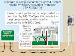
If overcurrent protection is provided at the SDS, then the installation must contain an equipment grounding conductor per Sec. 250.32(B)(1) [Sec. 250.32(B)(a)]. If overcurrent protection is not provided at the SDS, then the installation must comply with Sec. 250.30(A) [Sec. 250.32(B)(2)(b)] (Fig. 2).GEC size
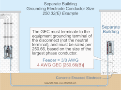
The GEC at a separate building must terminate to the equipment grounding terminal of the disconnect (not the neutral terminal). Size it per 250.66 based on the area of the largest phase conductor [250.32(E)].
Example question: What size GEC is required for a building disconnect supplied with a 3/0 AWG feeder with a concrete-encased electrode? (Fig. 3)
Answer: 4 AWG [Sec 250.66(B) and Table 250.66]
If the GEC is connected to a rod(s), the portion of the conductor that connects only to the rod(s) is not required to be larger than 6 AWG copper [Sec. 250.66(A)]. If the GEC is connected to a concrete-encased electrode(s), then the portion of the conductor that connects only to the concrete-encased electrode(s) is not required to be larger than 4 AWG copper [Sec. 250.66(B)].
Non-stationary generators
A portable generator is not required to connect to a grounding electrode (grounded) where all the following conditions are met [Sec. 250.34(A)]:
(1) The generator supplies only equipment and/or receptacles mounted on the generator.
(2) The normally noncurrent-carrying metal parts of equipment and the equipment grounding conductor terminals of the receptacles are connected to the generator frame.
A vehicle- or trailer-mounted generator is not required to be connected to a grounding electrode where all the following conditions are met [Sec. 250.34(B)]:
(1) The generator frame is bonded to the vehicle or trailer frame.
(2) The generator supplies only equipment or receptacles mounted on the vehicle, trailer, or generator.
(3) The normally noncurrent-carrying metal parts of equipment and the equipment grounding conductor terminals of the receptacles are connected to the generator frame.
High-impedance ground
High-impedance grounded 3-phase systems 480V up to 1,000V are permitted where all the following conditions are met [Sec. 250.36]:
(1) Conditions of maintenance and supervision ensure only qualified persons service the installation.
(2) The system has ground detectors.
(3) Only line-to-line loads are served.
To minimize fault current, high-impedance grounded systems usually have a resistor installed between the neutral point of the SDS and the GEC.
Error-free grounding and bonding on electrical power sources
To avoid grounding and bonding errors on electrical power sources such as transformers and generators, first determine whether the unit you are installing is an SDS. If it is not, then you bond it, and do not ground it. If it is an SDS, then you must ground it per the requirements that begin in Sec. 250.30.
About the Author

Mike Holt
Mike Holt is the owner of Mike Holt Enterprises (www.MikeHolt.com), one of the largest electrical publishers in the United States. He earned a master's degree in the Business Administration Program (MBA) from the University of Miami. He earned his reputation as a National Electrical Code (NEC) expert by working his way up through the electrical trade. Formally a construction editor for two different trade publications, Mike started his career as an apprentice electrician and eventually became a master electrician, an electrical inspector, a contractor, and an educator. Mike has taught more than 1,000 classes on 30 different electrical-related subjects — ranging from alarm installations to exam preparation and voltage drop calculations. He continues to produce seminars, videos, books, and online training for the trade as well as contribute monthly Code content to EC&M magazine.


