Each motor branch circuit must be protected against short circuit and ground faults by an overcurrent device sized no greater than the percentages listed in Table 430.52. A branch-circuit short-circuit and ground-fault protective device protects the motor, the motor control apparatus, and the conductors against short circuits or ground faults, but not against overload [Sec. 430.51].
The motor branch-circuit short-circuit and ground-fault protective device must comply with Sec. 430.52(B) and (C). A motor branch-circuit short-circuit and ground-fault protective device must be capable of carrying the motor’s starting current. Motor branch-circuit conductors must comply with Sec. 430.22.
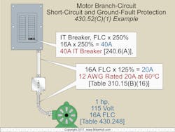
Example: What size conductor and inverse time circuit breaker are required for a 1-hp, 115V, single-phase continuous-duty motor? (Fig. 1)
Step 1: Determine the branch-circuit conductor, 125% of FLC
[Sec. 110.14(C)(1)(a)(1), Table 310.15(B)(16), Sec. 430.22, and Table 430.248]:
16A × 1.25 = 20A
A 12 AWG conductor is rated 20A at 60°C
Step 2: Determine the branch-circuit protection, 250% of FLC
[Sec. 240.6(A), Sec. 430.52(C)(1), and Table 430.248]:
16A × 2.50 = 40A
Use a 40A breaker.
What if the motor branch-circuit short-circuit and ground-fault protective device values derived from Table 430.52 don’t correspond with the standard overcurrent device ratings listed in Sec. 240.6(A)? In that case, you can use the next higher overcurrent device rating [Sec. 430.52(C)(1), Exception No. 1].
Branch-circuit conductors to a single motor must have an ampacity of at least 125% of the motor FLC as listed in Tables 430.247 through 430.250 [Sec. 430.6(A)].
The branch-circuit short-circuit and ground-fault protection devices are sized by considering the type of motor and the type of protection device and applying the percentage of the motor’s FLC as listed in Table 430.52.
Example: If an inverse time circuit breaker is used for short-circuit and ground-fault protection, what size circuit breaker and conductor is required for a 7½-hp, 230V, 3-phase motor?
Step 1: Determine the branch-circuit conductor, 125% of FLC.
[Sec. 110.14(C)(1)(a)(1), Table 310.15(B)(16), Sec. 430.22, and Table 430.250]:
22A × 1.25 = 28A, 10 AWG rated 30A at 60°C
Step 2: Determine the branch-circuit protection, 250% of FLC.
[Sec. 240.6(A), Sec. 430.52(C)(1), and Table 430.250]:
22A × 2.50 = 55A
Next size up says use a 60A inverse-time breaker.
Combined Overcurrent Protection
A motor can be protected against overload, short circuit, and ground faults by a single overcurrent device sized to the overload requirements contained in Sec. 430.32 [Sec. 430.55].
Example: What size dual-element fuse is permitted to protect a 5-hp, 230V, single-phase motor with a service factor of 1.15 and a nameplate current rating of 23.50A from overloads as well as short circuits and ground faults?
Overload protection [Sec. 430.32(A)(1) and Sec. 430.55]
23.50A × 1.25 = 29.40A
The fuse can’t be larger than 29.40A [Sec. 430.32(A)(1)]; therefore, use a 25A fuse [Sec. 240.6(A)]
Feeder Short-Circuit and Ground-Fault Protection
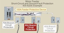
Feeder conductors must be protected against short circuits and ground faults by a protective device sized not more than the largest rating of the branch-circuit short-circuit and ground-fault protective device for any motor, plus the sum of the full-load currents of the other motors in the group [Sec. 430.62(A)]
Example: What size inverse-time circuit breaker is required for feeder protection for the following motors? Both motor branch circuits have inverse-time circuit breakers.
Motor 1: 7½ hp, 230V, 3-phase: FLC = 22A [Table 430.250]
Motor 2: 5 hp, 230V, 3-phase: FLC = 15.20A [Table 430.250]
Feeder protection [Sec. 430.62(A)] is to be sized no greater than the largest branch-circuit ground-fault and short-circuit overcurrent device plus the other motors’ FLC.
Step 1: Determine the largest branch-circuit ground-fault and short-circuit overcurrent device [Sec. 430.52(C)(1) Ex].
7½-hp motor = 22A × 2.50 = 55A, next size up 60A
5-hp motor = 15.20A × 2.50 = 38, next size up = 40A
Step 2: Determine the size of the feeder protection device.
Not more than 60A + 15.20A = 75.20A,
Next size down = 70A [240.6(A)]
The “next-size-up protection” rule for branch circuits [Sec. 430.52(C)(1), Exception No. 1] doesn’t apply to the motor feeder overcurrent device rating.
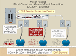
Example: What size inverse-time circuit breaker is required for feeder protection required for the following motors? All motors branch circuits have inverse-time circuit breakers (Fig. 2).
Motor 1: 7½-hp, 208V, 3-phase: FLC = 24.20A [Table 430.250]
Motor 2: 5-hp, 208V, single-phase: FLC = 30.80A [Table 430.248]
Motor 3: 1 hp, 115V, single-phase: FLC = 16A [Table 430.248]
Size your feeder protection [Sec. 430.62(A)] no greater than the largest branch-circuit ground-fault and short-circuit overcurrent device plus the other motors’ FLC in the same group.
Step 1: Determine the largest branch-circuit ground-fault and short-circuit overcurrent protection device [Sec. 430.52(C)(1) Exception].
7½-hp motor = 24.20A × 2.50 = 60.50, round up to 70A
5-hp motor = 30.80A × 2.50 = 77A, round up to 80A
1-hp motor = 16A × 2.50 = 40A
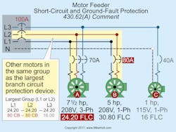
Step 2: Determine the size of the feeder protection device based on the largest group of motors. To determine the group, you need to balance out the motors between L1, L2, and L3 (Fig. 3).
Not more than 80A + 24.20A = 104.20A,
Next size down = 100A [Sec. 240.6(A)]
The “next-size-up protection” rule for branch circuits [Sec. 430.52(C)(1) Ex 1] doesn’t apply to the motor feeder overcurrent protection device rating.
VA Calculations
The measure of the mechanical output of a motor is horsepower. Horsepower can be converted to watts by multiplying the horsepower rating by 746W per horsepower. Since this is a measure of a motor’s output, don’t confuse it with the input power required by a motor.
Example: What are the output watts for a dual voltage, 1-hp motor rated 115/230V?
(a) 746W
(b) 1,000W
(c) 1,400W
(d) 1,840W
Answer: (a) 746W
Output = 746W × hp
Output = 1 hp × 746W
Output = 746W
The input VA of a motor is determined by multiplying the motor volts by the motor amperes. To determine the single-phase motor VA rating, you can use the following formula:
Single-Phase Motor VA = Motor Volt Rating × Motor Ampere Rating
Example: What’s the input VA for a dual voltage, 1-hp motor rated 115/230V?
Per Table 430.248, 115V FLC = 16A, 230V FLC = 8A
VA at 230V = 230V × 8A
VA at 230V = 1,840VA
VA at 115V = 115V × 16A
VA at 115V = 1,840VA
Many people believe a 230V motor consumes less power than a 115V motor, but both motors consume the same amount of power.
To determine the 3-phase motor VA rating, use the following formula 3-Phase VA = Motor Volt Rating × Motor Ampere Rating ×1.732
Example: What’s the input VA for a 5-hp, 230V, 3-phase motor?
Per Table 430.250, FLC = 15.20A
Motor VA = 230V × 15.20A × 1.732
Motor VA = 6,055VA
Adjustable speed drives
Circuit conductors supplying power conversion equipment included as part of an adjustable-speed drive system must have an ampacity at least 125% of the rated input current to the power conversion equipment [Sec. 430.122(A)]. Overcurrent protection for adjustable-speed drive systems must be per manufacturer’s instructions [Sec. 430.130(A)(2)].
Example: What size branch-circuit conductors are required for an adjustable-speed drive system with a rated input of 25A when the terminals of the adjustable speed drive are rated 60°C?
Rated input from adjustable speed drive = 25A
Conductor = 25A × 1.25
Conductor = 31.25A, 8 AWG rated 40A at 60°C [Table 310.15(B)(16)]
Avoiding problems
You can see that correctly sizing the branch-circuit short-circuit and ground-fault protective devices for motor circuits depends on first correctly characterizing the motor. Assuming you’ve done that, and you’ve correctly sized the motor overcurrent protection, everything should work fine. Right?
Yes, but only if many other assumptions are also correct. For example, it’s a good practice to double check the motor application criteria to ensure you have the correct motor for the application. You save time if you do that before performing the calculations.
If later it turns out the branch-circuit protective device seems to nuisance trip, don’t first assume it’s undersized. Something in the power supply (e.g., failed power factor capacitor) or the load (e.g., gearbox problem) is likely causing that. Motor applications are complicated for these and other reasons. Work methodically when performing those calculations so that your calculation work isn’t the point of failure.
These materials are provided to us by Mike Holt Enterprises of Leesburg, Fla. To view additional Code training materials offered by this company, visit www.mikeholt.com.About the Author

Mike Holt
Mike Holt is the owner of Mike Holt Enterprises (www.MikeHolt.com), one of the largest electrical publishers in the United States. He earned a master's degree in the Business Administration Program (MBA) from the University of Miami. He earned his reputation as a National Electrical Code (NEC) expert by working his way up through the electrical trade. Formally a construction editor for two different trade publications, Mike started his career as an apprentice electrician and eventually became a master electrician, an electrical inspector, a contractor, and an educator. Mike has taught more than 1,000 classes on 30 different electrical-related subjects — ranging from alarm installations to exam preparation and voltage drop calculations. He continues to produce seminars, videos, books, and online training for the trade as well as contribute monthly Code content to EC&M magazine.


