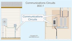
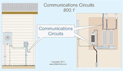
Article 800 covers circuits that extend voice, audio, video, interactive services, and outside wiring for fire alarms and burglar alarms from the communications utility to the customer’s communications equipment (Fig. 1). It doesn’t apply to communications utility equipment under the exclusive control of the communications utility [90.2(B)(4)]. Section 90.3 lets us know that Art. 800 is not subject to the requirements of NEC Chapters 1 through 7 unless a requirement from these chapters is specifically mentioned.
Dial “W” for workmanship
Install communications equipment and cabling in a neat and workmanlike manner [800.24], and don’t let cabling block access to equipment or ceiling areas [800.21].
Support exposed cables with supports that fasten to frame members, securing the cables with straps, staples, hangers, cable ties, or similar fittings [800.24]. Install these in a manner that doesn’t damage the cable.
You can support raceways and cables by independent support wires attached to the suspended ceiling per 300.11. Don’t use the ceiling-support wires or ceiling grid directly [300.11].
Don’t strap, tape, or attach communication wires or cables to raceways as a means of support. [800.133(B)].
Communications equipment must be listed [800.170]. Install it per manufacturers’ instructions per 110.3(B) [800.18]. Support hardware doesn’t have to be listed, but NFPA 90A-2009 has heat release and smoke emissions requirements for “cable ties” in Secs. 4.3.11.2.6.5 (plenums) and 4.3.11.5.5.6 (raised floor plenums) [800.24 Note 2].
Stop fire from spreading
These three Art. 800 requirements reduce the spread of fire or products of combustion:
• Tag future use cables. If you don’t terminate some cables because they are for future use, identify each with a tag that can withstand the environment [800.25]. This distinguishes them from abandoned cables.
• Remove abandoned cables. If a cable doesn’t terminate and isn’t for future use, remove the accessible portion [800.2]. Cables installed in concealed raceways aren’t accessible, so you don’t have to remove them.
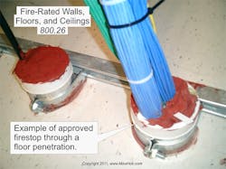
• Apply firestopping. Firestop openings in fire-rated walls, floors, and ceilings for electrical equipment. Use firestop material listed for the specific types of wiring methods and construction structures. Use firestop methods approved by the AHJ to maintain the fire-resistance rating of the fire-rated assembly [800.26], as shown in Fig. 2.
Cables entering buildings
Underground communications cables don’t need to be listed for wet locations [800.47].
Overhead (aerial) communications cables must have a vertical clearance of at least 8 ft from all points of roofs above which they pass [800.44]. This doesn’t apply to auxiliary buildings, such as garages. You can reduce this clearance to 18 in. if no more than
6 ft of overhead (aerial) conductors pass over no more than 4 ft of roof, and they terminate to a raceway mast or other approved support.
You can install unlisted communications cables in building spaces other than risers, ducts, or plenum spaces as described in 300.22(C) if the cable length within the building from the point of entrance doesn’t exceed 50 ft, and the cable terminates in an enclosure or primary protector [800.48]. However, there’s a catch. For each communications circuit, you must install a listed primary protector as close as practicable to the point of entrance [800.90(B)]. Thus, unlisted communications cables can’t enter the building if it’s practicable to place the primary protector closer than 50 ft to the point of entrance.
In installations where the communications cable enters a building, the metallic sheath members of the cable can be grounded as specified in 800.100, or they can be interrupted by an insulating joint or equivalent device as close as practicable to the point of entrance.
Grounding methods
Bond and ground the primary protector and the metallic member of cable sheaths per 800.100 (A) through (D). What does this entail? The two simplest requirements are:
(C) Comply with 250.70 when connecting to grounding electrodes.
(D) If you install a separate grounding electrode (for example, a ground rod) for a communications system, then bond it to the building’s power grounding electrode system with a minimum 6AWG conductor.
Section 800.100(A) provides requirements for the bonding or the grounding electrode conductor:
(1) Insulation. Must be listed.
(2) Material. Copper or other corrosion-resistant conductive material.
(3) Size. At least 14 AWG with a current-carrying capacity of not less than the grounded metallic sheath member or protected conductor of the communications cable. Not required to be larger than 6 AWG.
(4) Length. As short as practicable. For one- and two-family dwellings, the bonding conductor or grounding electrode conductor can’t be longer than 20 ft.
(5) Run straight. Run in as straight a line as practicable.
(6) Physical protection. The bonding conductor and grounding electrode conductor must not be subject to physical damage. If installed in a metal raceway, bond each end of the raceway to the contained conductor or connect the ends to the same terminal or electrode to which the bonding conductor or grounding electrode conductor is connected.
There is an exception for 800.100(A)(4). If the bonding conductor or grounding electrode conductor is more than
20 ft long for one- and two-family dwellings, then install a separate ground rod at least 5 ft long [800.100(B)(3)(2)] with fittings suitable for the application [800.100(C)]. Bond this to the power grounding electrode system with a minimum 6AWG conductor [800.100(D)].
Section 800.100(B) provides requirements for the grounding electrode for three types of applications:
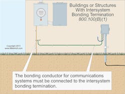
Structure with intersystem bonding termination (IBT). The bonding conductor for the primary protector and the metallic sheath of communications cable must terminate to the IBT as required by 250.94 (Fig. 3).
Structure without IBT. The bonding conductor or grounding electrode conductor must terminate to the nearest accessible:
(1) Building/structure grounding electrode system [250.50].
(2) Interior metal water piping system, within 5 ft from its point of entrance [250.52(A)(1)].
(3) Accessible means external to the building, as covered in 250.94 Ex.
(4) Nonflexible metallic service raceway.
(5) Service equipment enclosure.
(6) Grounding electrode conductor or the grounding electrode conductor metal enclosure of the power service.
(7) Grounding electrode conductor or the grounding electrode of a remote building/structure disconnecting means [250.32].
Structure without IBT or grounding means. The grounding electrode conductor must connect to:
(1) Any individual grounding electrode described in 250.52(A)(1), (A)(2), (A)(3), or (A)(4).
(2) Any individual grounding electrode described in 250.52(A)(6) and (A)(7), or to a ground rod not less than 5 ft long and ½ in. in diameter located at least 6 ft from electrodes of other systems.
Cables in buildings
Communications cables installed within buildings must be listed unless the length of the cable from its point of entrance does not exceed 50 ft as permitted by 800.48. You can install communications cables in any Chapter 3 raceway, following the requirements of Chapter 3 [800.110]. Raceway fill limitations of 300.17 do not apply to communications cables installed in a raceway. Alternatively, you can install the cables in a listed communications raceway if you do so per 362.24 through 362.56 (the rules for ENT).
If you install communications cables in fabricated ducts used for environmental air, you can choose from five permissible cable types. You can use up to 4 ft of Type CMP cable with no raceway restrictions. To use a longer run of CMP or to use CMR, CMG, CM, or CMX, the raceway must comply with 300.22(B). In plenum spaces used for environmental air, the requirements are similar but a bit more complex [800.113(B)].
Communications cables can be in the same raceway, cable tray, cable routing assembly, or enclosure as conductors of any of the following [800.133]:
• Optical fiber cables complying with Parts I and IV of Art. 770.
• Coaxial cables complying with Parts I and IV of Art. 820.
• Class 2 and Class 3 circuits complying with Parts I and III of Art. 725.
• Power-limited fire alarm circuits complying with Parts I and III of Art. 760.
Communications conductors can be within the same cable as Class 2 or Class 3 conductors, if the cables comply with Art. 800 [725.139(D)(1)].
Getting it right
To correctly apply Art. 800, begin by noting:
• Where exactly the point of entrance is.
• How far, in terms of cable run, the primary protector is (or will be) from the point of entrance.
• What other utility ground rods are present and whether those are bonded together.
Getting these few facts documented from the outset will help you avoid the most common communications cabling system mistakes.
Holt is the owner of Mike Holt Enterprises, Inc. in Leesburg, Fla. He can be reached at www.mikeholt.com.
About the Author

Mike Holt
Mike Holt is the owner of Mike Holt Enterprises (www.MikeHolt.com), one of the largest electrical publishers in the United States. He earned a master's degree in the Business Administration Program (MBA) from the University of Miami. He earned his reputation as a National Electrical Code (NEC) expert by working his way up through the electrical trade. Formally a construction editor for two different trade publications, Mike started his career as an apprentice electrician and eventually became a master electrician, an electrical inspector, a contractor, and an educator. Mike has taught more than 1,000 classes on 30 different electrical-related subjects — ranging from alarm installations to exam preparation and voltage drop calculations. He continues to produce seminars, videos, books, and online training for the trade as well as contribute monthly Code content to EC&M magazine.


