Often used and frequently misapplied, the rules for tapping feeders (NEC Sec. 240.21) continue to confuse many installers. First and foremost, it’s important to recognize these rules do not apply to service conductors and other conductors that do not meet the definition of a feeder as outlined in Art. 100.
Section 240.21 requires that overcurrent protection shall be provided in each ungrounded conductor at the point the conductor receives its supply or generally at the starting point of the circuit. The exception to this general rule of overcurrent protection at the point of supply is found in Sec. 240.21(A) through (H). This Section is where we find our tap rules that permit overload protection at the termination of the tap.
Tap rules in general
Electrical installers are typically involved with taps that are 10 ft or less in length or more than 10 ft but not exceeding 25 ft in length. In some cases, such as outdoor settings, taps are permitted in longer lengths. So, what’s the deal with the distance limitation, and why is the distance important?
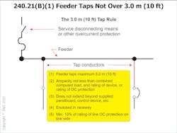
The length of the tap, along with the size of the tap conductor, are major factors in determining the overall impedance of the tap conductor. Why? The tap conductor is generally smaller than the feeder conductor from which it is tapped. When applying the 10-ft tap rule (Fig. 1), the tap conductor may be as small as one-tenth the size of the overcurrent device protecting the feeder from which the tap is made [Sec. 240.21(B)(1)(4)]. When applying the 25-ft tap rule (Fig. 2), the tap conductor may be as small as one-third the size of the overcurrent device protecting the feeder from which the tap is made [Sec. 240.21(B)(2)(1)].
Overcurrent and overload protection
Where is the ground-fault short-circuit protection for the tap? The OCPD is protecting the feeder ahead of the tap. If the impedance of the feeder (and the potentially much smaller tap conductor) is too great, the feeder and its tap will not carry enough current with a fault on the tap conductors to open the overcurrent device upstream that protects both the feeder and the tap conductors. In short, the reason for the size — one-tenth on the 10-ft tap rule and one-third on the 25-ft tap rule — is that these limitations have been demonstrated as sufficient conductor size and length to carry enough current to open the upstream feeder overcurrent device providing the necessary ground-fault/short-circuit protection of the circuit in the event of a fault on the tap conductor.
Now that we’ve addressed ground-fault and short-circuit protection, we are left with the final component of overload protection for the tap conductor. Overload protection is provided at the termination of the tap, which is often a fusible switch in a main breaker-type panelboard that is not greater than the ampacity of the tap conductor.
Section 240.4 generally permits the overcurrent device protecting a conductor to be rounded up to the next higher standard overcurrent device, up to 800A, in the event the conductor does not correspond to a standard size as noted in Sec. 240.6. With tap rules and transformer secondaries, DO NOT round up. Section 240.21(B) and (C) clearly state the rules of Sec. 240.4(B) do not apply. If we were to ignore the rule and round up anyway, our tap conductor may be smaller than the minimum size necessary to trip the overcurrent device in the event of a fault.
Sizing the equipment grounding conductor
The last element to address is probably the most often missed: sizing a wire-type equipment grounding conductor (EGC) or supply-side bonding jumper installed with the taps. This sizing is often done incorrectly, resulting in an undersized conductor. The EGC for tap conductors is sized based on the upstream overcurrent device, protecting the feeder from which the tap is made. Remember: If there is a fault on the tap conductor, the overcurrent device protecting the upstream feeder is the device that must trip. An example might be that if you tap a feeder protected at 1,000A, the EGC installed with the taps must be sized from Table 250.122 based on a 1,000A overcurrent device. Keep in mind the EGC per Sec. 250.122 is not required to be larger than the ungrounded tap conductors.
When addressing the transformer secondary conductors as found in Sec. 240.21(C), you generally do not have a wire-type EGC routed with the secondary taps — instead, there’s a supply-side bonding jumper. This conductor performs many of the same functions as an EGC; however, it is sized based on Table 250.102(C). Using Table 250.102(C) based on the size of the transformer secondary conductors will nearly always result in the need for a larger size supply-side bonding jumper than an EGC sized per Table 250.122.
Although this article does not address every possible scenario that may arise with tap conductors or transformer secondary conductors, a clearer understanding of this information will keep designers, inspectors, and installers on the right track.
For more information on this topic, read “Why Tap a Feeder in the First Place.”
David Humphrey is certified as a 1&2 Family, General Electrical Inspector, Electrical Plans Examiner, and he holds a Virginia Master Electrician’s certification. He currently serves as an electrical plan review engineer. He can be reached at [email protected].
Inspector Intel articles are provided by the International Association of Electrical Inspectors (IAEI), www.iaei.org, a membership-driven, non-profit association headquartered in Richardson, Texas, that promotes electrical safety throughout the industry by providing education, certification of inspectors, advocacy, partnerships, and expert leadership in electrical codes and standards.
About the Author

David Humphrey
David G. Humphrey began his career in the electrical industry in 1978 where he worked as an electrician for 10 years. He became an electrical inspector for Henrico County, Va., in 1988 and was promoted to the senior electrical inspector in 1995. In 2005, David was promoted to his current position as electrical plan review engineer.
David has served IAEI as a Virginia Chapter President and Southern Section President. He is certified as a 1&2 Family, General Electrical Inspector, Electrical Plans Examiner, and he holds a Virginia Master Electrician's certification. David was an electrical apprentice instructor in Richmond, Va., from 1989 until 2005, and he additionally served as an advanced electrical instructor for the Virginia Department of Housing Code Academy.
David has conducted numerous electrical seminars and training programs for the Virginia Chapter IAEI, and he now serves as a seminar instructor for the IAEI International Office. David serves on the NCPCCI Electrical Exam committee; he has served as the principal IAEI representative on CMP 8 for the 2008 and,2011 NEC cycles. David has also served as the IAEI representative and Chair of CMP 9 for the 2014, 2017, and 2020 NEC. David is currently the chair of CMP-2 for the 2023 cycle.


