Why Connecting a PV System Can Be Confusing
The increase in size of solar photovoltaic (PV) systems in recent years has made it more difficult to install the AC output into existing building panelboards, either at the electrical service location or at sub feed panelboard locations. The basic reason for this is the restriction on not loading the panelboard bus assembly to more than 120% of its rating from a summation of all power sources standpoint. To compensate for this, many PV system designers and installers are leveraging National Electrical Code (NEC) allowances to connect energy sources ahead of the service or feeder disconnecting means. These allowances are covered in Sec. 230.82 for services, which reads, in part, as follows:
“Only the following equipment shall be permitted to be connected to the supply side of the service disconnecting means: (6) Solar photovoltaic systems, fuel cell systems, or interconnected electric power production sources.”
So what constitutes a “service”? This is answered in the definitions area of Art. 100.
“Service. The conductors and equipment for delivering electric energy from the serving utility to the wiring system of the premises served.”
As you can see, to be considered a service, the source of power must be an electric utility distribution system.
With that in mind, how are these installations sized, and are there any other methods to interject premises on-site power sources into the electrical supply system? NEC Art. 705 [Interconnected Electric Power Production Sources] covers this topic. The first thing you will notice from the title of this Article is that it applies to any on-site power source, not just PV systems.
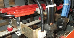
Section 705.12 contains the prescriptive requirements for interjecting power sources from the output of the electric utility interactive inverter into the premises electrical system. Section 705.12(A) deals with connections ahead of or on the supply side of a service main disconnect (Photo 1). The requirements here are simple, as the sum of any overcurrent devices for the power production sources cannot exceed the rating of the service. The rationale here is that although the service disconnect will limit the current provided on the line side, the power production sources will send any additional current out on the electric utility power system. Because of this situation, the available current must not be more than the conductors can carry. There is also a concern here relative to available fault currents that these conductors may be subject to.
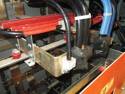
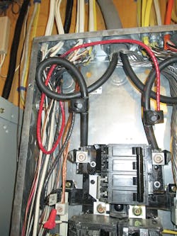
Many people believe that PV systems can generate large fault currents like those found on electric utility distribution systems. That is not true, as PV systems are power limited. And, if the conductors are properly sized, they will always be larger than the maximum current that the PV system can generate. The real concern with conductors from alternative energy systems connected ahead of the service disconnect is the potential for them to be exposed to fault currents generated on the utility side of the meter. To compensate for this, language was added in Sec. 705.31 of the 2014 NEC to limit the conductor length to 10 ft (Photos 2 and 3). There is also an exception allowing these conductors to be more than 10 ft in length if they are protected at their point of connection to the service conductors by either cable limiters or current-limited circuit breakers. A first revision was made to this Section for the 2020 NEC, which moves the requirements to the new Sec. 705.11 and revises the overcurrent device location.
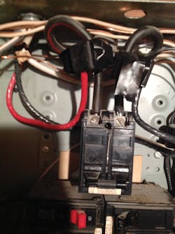
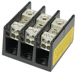
The other item to remember here is that many people are using power distribution blocks to make these connections (Photo 4). These are good products, but per the UL product listing (see OPQS), these devices are rated 1,000V or less and in systems with available fault current of 10,000A or less unless labeled otherwise. The product standard also recognizes power distribution blocks for use on both the supply side and the load side of the service disconnect. However, if used on the supply side, power distribution blocks must be checked and verified that they are acceptable for use at this point in the system.
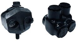
Installers are also using a variety of insulation piercing and threaded lug type connectors to make these connections (Photo 5). My research has shown that this type of connector is covered under UL 486 A/B, and they are limited to use at 600V or less. It also has shown that there are no evaluations on this type of connector for limiting the use ahead of the service main or fault current ratings.
Many factors must be considered when using this type of connector, the most important of which relates to proper torque requirements in accordance with the manufacturer’s instructions. It’s also important that the manufacturer’s instructions be followed regarding the way the connectors are being used. Other NEC requirements to consider include wire bending space, splices, taps, and conductors in the cross-section of a wiring space within a panelboard not to exceed 75% of that area (Sec. 312.6).
The other concern that arises is what these conductors are called. Many want to identify these interconnection conductors as “Service Conductors.” To clarify this again, let’s look at the definitions found in Art. 100:
“Service Conductors. The conductors from the service point to the service disconnecting means.”
“Service-Entrance Conductors, Overhead System. The service conductors between the terminals of the service equipment and a point usually outside the building, clear of building walls, where joined by tap or splice to the service drop or overhead service conductors.”
“Service-Entrance Conductors, Underground System. The service conductors between the terminals of the service equipment and the point of connection to the service lateral or underground service conductors.”
When using these definitions, it is clear these conductors do not meet the definition of “Service Entrance Conductors,” yet many interpret these to be service entrance conductors. The following exception to Sec. 230.40 adds further confusion to this situation.
“Exception No. 5: One set of service-entrance conductors connected to the supply side of the normal service disconnecting means shall be permitted to supply each or several systems covered by 230.82(5) or 230.82(6).”
Considering these to be service entrance conductors would require you to modify the sizing process and other items that are intended when supplying electric utility power to connected loads.
To add clarity on this issue, a new Section [705.11 Supply-Side Source Connections] has been added during the first revision stage for the 2020 NEC. This new Section is intended to address some of these concerns, and if accepted will require a minimum conductor size of No. 6 CU and the wiring methods defined in Sec. 230.43 to be used.
As mentioned above, regardless of what these conductors are called, the two most important considerations are to be certain that they are sized large enough for 125% of the inverter output current — and that means to address any available fault currents are part of the installation.
Section 705.12(B) establishes requirements for connections made on the load side of the service disconnect. Some of these requirements in the 2017 NEC are the same as they have been in previous editions; however, there are some new and different requirements.
705.12(B)(1) remains predominately unchanged other than clarification that more than one inverter supply can be connected on the load side of the service disconnect of a building. Whether there is one or more than one, they each must terminate in either a dedicated circuit breaker or fusible switch. Remember, the on-site power supplies are not limited to PV systems only.
705.12(B)(2) deals with connecting into either feeder conductors or busbars with some clarification on how feeders that are part of taps regulated by
Sec. 240.21 are calculated. This Section also establishes that for all the calculations listed, the ampacity rating of 125% of the inverter maximum output rating shall be used. If the connection is made into a feeder, the word connection is important here, as many people call these taps, and they aren’t taps. If the connection is made between the overcurrent device protecting the feeder and the load terminations, the installation must meet one of the following requirements:
• The feeder conductors must be large enough to carry the total ampere rating of the feeder overcurrent device and 125% of the maximum rated output current of the inverter(s).
• The feeder conductors terminate in an overcurrent device at their load end no larger than the ampere rating of the conductors.
When evaluating these two options, all the other requirements for properly protecting the feeder conductors and inverter output conductors must be considered, and the calculations for continuous loading and conditions of use must also be evaluated.
705.12(B)(2)(2) covers the requirements for taps that are connected to feeders that also support the connection of alternative energy sources. As stated above, the connection of alternative energy systems into feeders are not the taps being addressed here, as they are not taps. What is being addressed is a feeder tap that is made in accordance with Sec. 240.21, and the feeder also has an alternative energy source connected to it. In these cases, the sizing of the tap must be based on feeder overcurrent device and 125% of the inverter output rating.
For example, let’s say you had a 400A overcurrent device protecting a feeder, and you added an inverter output circuit with the maximum inverter output rating being 100A. From this feeder, you are going to make a tap using the 25-ft tap rule [240.21(B)]. These tap conductors would have to have an ampacity of at least 175A (i.e., 525 ÷ 3). The 525A would be derived by adding the existing overcurrent device rating (400A) and 125% of the inverter output (100A × 1.25).
In smaller systems, the most common method used for interconnecting alternative energy sources and electric utility power is through circuit breakers that are attached to panelboard busbars. There are a few different ways to accomplish this with the most predominant concern being that the busbars are not overloaded. The first bit of information that is needed for busbar connections is the maximum current rating of the busbars. This is typically found on the labels the manufacturer installs within the panelboard. However, if there is any confusion, the manufacturer can provide actual information relative to the ratings of their products.
The first NEC requirement is in Sec. 705.12(B)(2)(3)(a), which is straightforward. If the combined rating of the overcurrent device for the feeder supplying the panelboard and 125% of the maximum inverter output rating do not exceed the busbar rating, the connections can be made anywhere in the panelboard.
The second NEC requirement in Sec. 705.12(B)(2)(3)(b) covers the common practice of installing the two sources, feeder and inverter output, at opposite ends of the busbar. If this method is used, the combination of the feeder overcurrent device and 125% of the inverter output cannot exceed 120% of the panelboard busbar rating. For example, if you had a panelboard with busbars rated 225A, the maximum total supplied current cannot exceed 225A × 1.2, or 270A. This being the case, if the feeder was protected by a 200A circuit breaker, the total inverter output could not exceed 70A (270A – 200A) times 0.8 (the inverse of 125%), or 56A. This is an easy method that could be used to figure the maximum amount of alternative power that could be fed into an existing panelboard.
A new Section was added in the 2017 NEC to clarify that this same methodology can be used for a center-fed panelboard. Section 705.12(B)(2)(3)(d) reads as follows:
“(d) A connection at either end, but not both ends, of a center-fed panel board in dwellings shall be permitted where the sum of 125% of the power source(s) output circuit current and the rating of the overcurrent device protecting the busbar does not exceed 120% of the current rating of the busbar.”
Another thing to be cautious about when applying these requirements is the listed busbar rating of the panelboard. For example, when a panelboard is assembled by a manufacturer with 225A busing — and a factory installed 200A circuit breaker is installed ahead of the busing — the bus rating may then be limited to the 200A rating. The way to determine this is to look at the labeling inside the panelboard, contact the manufacturer, or the testing lab that listed the panelboard.
Although this article is focused on PV systems, Art. 705 covers any on-site power production system that interfaces with an electric utility supply and how they interconnect.
Rogers is the owner/operator of Bay State Inspectional Agency, Vineyard Haven, Mass. He is an active instructor for IAEI, the wiring inspector for the town of Oak Bluffs, and the Chair of NEC Code-Making Panel 4. He can be reached at [email protected].
About the Author
Jim Rogers
Owner
Jim Rogers has more than 50 years of experience in the electrical profession is a licensed journeyman and master electrician, a nationally certified electrical inspector, and an associate electrical engineer. He has managed the Massachusetts Electrical Board and serves on both state and national code committees. He is currently the electrical inspector for the town of Oak Bluffs, Mass., and operates a private inspection and investigation company, Bay State Inspectional Agency.
Rogers represents the International Association of Electrical Inspectors (IAEI) as the chair of NEC Code Making Panel (CMP) 4 for the National Fire Protection Association (NFPA), which has purview over photovoltaic systems and other alternative energy systems. Prior to being assigned to CMP 4, in 2000 he was the alternate to Andy Cartel on CMP 12. He also serves on the NFPA 303 Committee on Boatyards and Marinas. Rogers currently instructs for IAEI. He has previously taught for the International Brotherhood of Electrical Workers (IBEW) and served as an adjunct professor at the Benjamin Franklin Institute of Technology in Boston.
In addition, he has over 40 years of experience in the fire service and retired for the fire service with the rank of assistant chief, as well as serving as the department investigator and team leader for the County Fire Investigation Team. Rogers is a nationally certified fire investigator and certified fire and explosion investigator, as well as a state-certified fire inspector. He also has a bachelor’s degree in fire science from the University of Maryland.
