Top Tips to Improve Your Electrical Troubleshooting Skills
We’ve all had those long days where you wish you could just find the electrical problem and get to the next job — or go home! The best way to try and avoid these frustrating days is to review prints beforehand, stay abreast of the latest troubleshooting technologies, and understand that some problems are not easily diagnosed but hidden in the distribution system.
Electrical prints may contain more information than you first realize. Choosing the best test tools to locate and diagnose the issue will not only help reduce troubleshooting time but also provide much more detailed information to help solve a problem. In some cases, you may have to dig into the distribution system itself and determine if the power being delivered to loads is of good quality. Reducing downtime is an important business goal, and so is increasing your comfort level with your troubleshooting abilities.
Interpret the prints — and know the system
To spend time troubleshooting a control problem only to find out you have been barking up the wrong tree is truly frustrating. Interpreting an electrical diagram is more than just identifying the symbol types and component numbers. First, use the symbols and current flow path to determine the system operation. Pay attention to additional information, such as equipment numbers, and location. Then, use a systematic and logical approach to trace through the circuit with a digital multimeter (DMM). Typically, you look for the “missing voltage.” That is, if there is no voltage at a component and there should be, then where did it get lost?
Knowing the symbols is a must. If not accompanying the diagram, many resources are available to identify drawing symbols. Though equipment manufacturers may use somewhat different types of layout schemes, the purpose of the electrical schematic is to depict the sequence of operation of the system’s electrical components. Being able to follow this sequence and identify where the system faults are is what troubleshooting is all about. The ladder diagram is one of the most common arrangements for depicting the operation of a circuit and is basic for understanding all types of electrical schematics.
Using Fig. 1 as an example, notice the information that is available to reduce troubleshooting time. This system is spread out through a chemical plant. However, there is information that could send you to the best location to start the troubleshooting process.
- Understand the overall operation of this ladder diagram: Current flows into the circuit from X1 through the 10A fuse, down the power rail on the left, across the 1052 rung of the ladder through the 3612 R1 relay coil, then through the X2 return rail on the right and back to its source at X2.
- The overall operation of the component is evident: The PS-1 pressure switch contacts close to energize the 3612 R1 relay coil.
- The legend identifies not only the meaning of the symbols but also the location of all components in the plant.
- Once at the correct panel, the ladder diagram identifies the individual terminal strip and the terminal number for each specific wire.
- When the coil is energized, the numbers to the right of the ladder rung indicate that the relay contacts operated by the coil are electrically connected in lines 1053 and 1057 of the ladder diagram.
- To check whether a voltage is being applied to the PS-1 pressure switch, you could go into the field, find the switch, and, assuming it is convenient to access, remove the cover and check for the presence of voltage at terminal 1 of the switch. Or you could just (safely) open the main control panel and test for voltage on terminal strip 36P, terminal number 69.
- This ladder diagram is well over 1,000 rungs long. Based on your knowledge of the system, you should decide to start troubleshooting at the most logical point that makes sense for you. The more you know about the system, the quicker you can expect to find the problem.
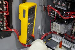
Photo 1 is a practical application of using the DMM for troubleshooting. Tracing through a circuit often goes quite quickly. Time can be saved by using a magnetic strap or other means to place the test instrument in a convenient location. Placing the black test lead (black for conventional purposes only) to the control circuit Common (X2) port, the red test lead can be used to go from terminal to terminal as identified on the print to check for voltage.
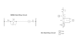
The use of IEC prints is common, depending upon the equipment manufacturer. The components and the electricity obviously still work the same, but the symbols are different. Figure 2 is a comparison of drawings between a NEMA start-stop circuit and an IEC start-stop circuit for energizing a starting contactor. If you troubleshoot using IEC prints, be sure you are familiar with these symbols. The troubleshooting methodology remains the same.
Safety Tip: While following lockout/tagout procedures, reading resistance is always the preferred method for troubleshooting — although it’s not always feasible. Most often control circuits must be energized for troubleshooting. Be sure to follow your electrical safety rules for diagnostic testing when working on energized circuits (see Sidebar below, “Troubleshooting Methods Have Evolved”).
Use the right test equipment properly to get the right data
It is said that “experience is the best teacher — as long as it is someone else’s experience.” Case in point: An electrician tested a 3-phase AC induction motor onboard a nuclear submarine. The electrician pronounced the windings were shorted, and the motor needed to be replaced. A hole was cut in the titanium hull to remove and replace the motor. To diagnose the problem, the electrician disconnected the motor from its source and then measured resistance phase-to-phase at the motor leads. He noticed very low resistance values. Resistance values were consistent between all phase-to-phase measurements. Therefore, the electrician diagnosed that the windings were shorted together due to the low resistance, and the motor needed replacement.
By using only a DMM and not understanding the construction of the motor, the electrician jeopardized the success of a mission — and at a significant financial cost. Similar mistakes are no doubt made every day throughout the industry. Training and knowledge of the latest technologies can help prevent such costly errors.
While the DMM is a valuable tool for the first analysis of motor windings, a more detailed test, such as a surge comparison test can accurately diagnose winding issues. The surge comparison tester injects a high-voltage signal into an individual phase winding. As the waveform decays there should be only one waveform present on the screen of the surge comparison tester. The appearance of a second waveform indicates a potential problem. See Fig. 3 for examples.
- Know your equipment. OSHA, the NEC, and NFPA 70E all require qualified persons to be knowledgeable in the construction and operation of their equipment. Learn to be inquisitive and be open to all learning opportunities.
- Select test tools and methods that give the most complete data to make a decision.
- Know your test equipment and how to interpret the results.
Think about power quality
When a load does not operate properly and there are no apparent causes, the quality of the electrical distribution power should be investigated. Just a few short decades ago, power quality issues were relatively unheard of. Other than brownouts and blackouts, the quality of the power delivered to incandescent lamps and motors was of little concern. However, the grid is no longer loaded with just motors and incandescent lamps.
Electronic loads, such as variable-speed drives, battery chargers, data servers, and electronic ballasts, produce currents that flow back into the facility distribution system. Those currents flow back in at multiples of the primary frequency of 60 Hertz (Hz) — 3 times 60 Hz equals 180 Hz, or the third harmonic; 300 Hz would be the fifth harmonic, etc. The effects of harmful harmonic frequencies include overheated neutrals and transformers, motor inefficiency, and misoperation of electronic equipment. Other power quality issues include voltage transients, sags and swells, and distortion of the primary 60 Hz sine wave.
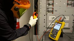
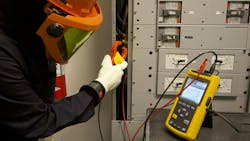
The use of a power quality analyzer is not difficult (see Photo 2). Interpreting the results and comparing them to standard maximum values requires knowledge obtained through training. Analyzing and interpreting power quality data is the first step in solving some of the more significant power distribution issues.
In summary, increase your troubleshooting skills to become more efficient and reduce downtime. Study electrical diagrams before the problems arise. Know how the system operates, and realize there may be information on the print that can help streamline the troubleshooting process. Select test tools that provide the most complete data to help diagnose problems. Understand that power quality problems do exist and can be isolated and corrected. You may never solve all the world’s electrical problems, but following some basic tips can reduce downtime and satisfactorily get you to your next goal.
Troubleshooting Methods Have Evolved
The Good Old Days
Here’s a quote from the 1942 edition of the American Electrician’s Handbook.
“Electricians often test circuits for the presence of voltage by touching the conductors with the fingers.” The handbook then describes the “proper” methods to perform this including “tasting” low voltages.
Yipes!
NFPA 70E First Addresses Testing
In the 2000 edition of the NFPA 70E, Standard for Electrical Safety in the Workplace, a new section on test equipment stated, “Test instruments and equipment and all associated test leads, cables, power cords, probes, and connectors shall be visually inspected for external defects and damage before the equipment is used on any shift.” Subsequent editions begin to revise and expand the requirements.
What does NFPA 70E say today?
The 2024 edition of the standard requires that only qualified persons may use test equipment and that an inspection must be made “before each use.” Also addressed are rating and design requirements, repairs, and operation verification. The standard requirement is not specific to multimeters but applies to all types of test equipment from non-contact detectors to surge comparison testers and power quality analyzers.
About the Author

Randy Barnett
CESCP
Randy Barnett is a master electrician, ICC Commercial Electrical Inspector, NFPA-certified Electrical Safety Compliance Professional and has worked as an electrician and technician in nuclear and coal-fired power plants, government nuclear research facilities, and in industrial maintenance and construction. He is the author of Commercial and Industrial Wiring – American Technical Publishers, numerous articles, and the producer of a monthly Tech Talk video series for EC&M Magazine. Randy provides training and program development services for clients such as, NTT Training, ABB, American Polywater, Socomec, and Schneider Electric. Randy can be reached at www.randybarnett.net.


