Beginning June 8 and ending around July 1, 2008, extensive flooding in the Midwest devastated cities such as Cedar Rapids and Iowa City, Iowa. Referred to by many as “Iowa's Katrina,” the flood waters brought about massive destruction the area had not seen in hundreds of years.
When industrial facilities are faced with such a catastrophic event, specific and detailed steps must be taken to return the facility to productive operation. In the wake of this type of natural disaster, it's especially critical to analyze and repair the electrical power system in a safe and logical sequence (see SIDEBAR: Temporary and Emergency Power). Following is an overview of how to approach recovery operations of electrical equipment after a flood.
Initial damage assessment
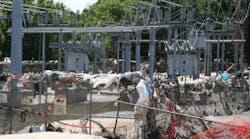
The first order of business in assessing water damage to the electrical equipment in any industrial plant is to gather all pertinent drawings and documentation available and perform a walkthrough of the entire electrical infrastructure. However, at times, drawings and documentation may not be available due to destruction (Photo 1). In this case, walkthroughs must be performed through tribal knowledge of plant personnel. Keep in mind the initial assessment is preliminary in nature, and an absolute understanding of the damage will not be gained until the equipment is disassembled in its entirety.
During the walkthrough, compile a list of flooded equipment to help you estimate man-power requirements and create a preliminary schedule of repair work. As mobilization of crews begins, start developing job strategies, such as finding office space, living accommodations, and transportation for crews. You must also think about arranging food/catering services and developing work schedules. Once your crews have been mobilized and job-site safety requirements are met (see SIDEBAR: Developing a Safety Plan Following a Natural Disaster), it's time to go to work.
Documentation is key
Second to safety, documentation is critical to the success of a project of this magnitude. All electrical equipment must be properly documented prior to removal to ensure it is reinstalled properly. This documentation process includes:
-
Tagging each piece of equipment.
-
Labeling all control and power wires.
-
Taking digital pictures of each piece of equipment.
-
Sketching an accurate diagram of each piece of equipment on the electrical equipment drawing sheet.
-
Filling out an electrical equipment tracking form.
-
Saving all pictures on a local database.
-
Filing the electrical equipment drawing sheet.
-
Creating a master electrical equipment tracking document.
-
Managing shipping documents for all electrical equipment.
Tag each piece of equipment and fill out all pertinent information, including sequence number, plant identification number, plant description, date, power center, or room number. Use a medium-point sharpie so that the information is legible, and then attach it to the equipment with a tie wrap.
Label all control wires with wire numbers and the power wires with phasing tape. Make sure each side of the termination is identified to ensure wiring will be connected correctly later.
Once the equipment is tagged and the wires are labeled, take two pictures of each piece of equipment. The first picture should include the tag in the picture (Photo 2), making sure the tag is legible and the picture is clear.
The second is for the sole purpose of wire clarification/documentation during the reinstallation process and should include all wiring associated with the bucket (Photo 3). Do not include the tag in the second picture, because it will obstruct visibility of the wiring information.
The next step is to sketch an accurate drawing of the piece of equipment on an electrical equipment drawing sheet. Include job name, job number, power center, sequence number, plant equipment number, plant description, technician name, date, and enough room to sketch the piece of equipment.
After a sketch is made of the piece of equipment, add the equipment to a detailed electrical equipment tracking sheet, which should include general information such as the item number, sequence number, priority, area of the plant, power center or room number, transformer, substation, cell position, equipment type, circuit identification, plant identification number, manufacturer, percent water level, model number, frame size, and voltage. After completing these procedures on all the equipment associated with a power center or a piece of gear, the QA/QC leader must review the documentation for accuracy. Once the documentation has been approved, the equipment is ready for removal.
Equipment removal
Each day, technicians should turn in field data to a project documentation manager (Photo 4). The field data should include the camera memory stick, electrical equipment drawing sheets, and electrical equipment tracking forms.
The project documentation manager should make sure the camera memory sticks are downloaded to a folder located on the site server. Each picture will be opened and saved in a folder labeled by the appropriate power center or room number. There are two pictures associated with each piece of equipment, both of which should be labeled using the sequence number. After saving the pictures on the local server, the memory sticks will be erased and ready for use the next day.
Next, turn in the electrical equipment drawing sheets, pair them with the digital pictures, and file all information. This is used to create installation packages for each power center, which will remain there until the reinstallation process begins.
During the documentation process, you must make decisions pertaining to each piece of damaged equipment. Can the equipment be repaired, or does it need to be replaced? Can the repairs take place on-site, or does the equipment need to be sent back to the shop?
A good source to be familiar with is the National Electrical Manufacturers Association (NEMA) publication, “Evaluating Water-Damaged Electrical Equipment,” which provides information on how to properly evaluate water-damaged electrical equipment (click here to see Table).
After consultation with the manufacturer, some larger types of electrical equipment may be reconditioned by properly trained personnel. Keep in mind the potential to recondition such equipment may vary with the nature of the electrical function, degree of flooding, age of the equipment, and length of time the equipment was exposed to water.
Motor repair
Motor repair is a major component of any flood recovery project (Photo 5). The documentation and handling process for this type of equipment is similar to other electrical equipment; however, there are additional items you must address. The documentation process for motors should include:
-
Record nameplate data and location of the motor.
-
Tag the base and motor with a unique sequence number that can be used to match up the new motor with the one it's going to replace.
-
Mark and record electrical connections.
-
Record coupling information and condition of coupling.
-
Mark and record shim information.
-
Collect all mounting hardware, couplings, and shim, and store in its own labeled container (usually ziplock plastic bags). This equipment should remain on-site and stored in a central location.
Ship each motor to a local motor shop for repair/replacement. While NEMA does recognize that motors can be repaired from damaged caused by water, it's not always economical to repair them. A cost analysis should be performed to help drive this decision.
Additional considerations
After this type of catastrophic event, it's typically best to replace certain types of equipment rather than try to recover items such as receptacles, light switches, start-stop stations, fire alarm panels, and metering equipment. Your crews must also drain all the conduits by opening up the conduit covers and letting gravity drain out all water and debris.
You should also test the insulation resistance of all control wiring, including the wiring from the start-stop stations back to the motor control center buckets and the plant DCS system. Be careful not to back-feed the electronics during this process, and replace cables that show low insulation resistance during testing.
It is possible to recover from a catastrophic event with a more reliable system than before. However, the speed and efficiency of the recovery will depend on the availability and accuracy of documentation. In preparation or planning for the recovery of an electrical system, the facility should ensure that all drawings/documentation are up to date and a copy is kept in a safe location that can be accessed after the event.
Editor's Note: The original version of this article, which included a case study analysis of the Cedar Rapids flood, was presented at the PowerTest Conference held March 2009 in San Antonio (www.powertest.org).
Beisert is production manager of the engineering service division at Shermco Industries, Irving, Texas. He can be reached at [email protected].
SIDEBAR: Temporary and Emergency Power
When a disaster of this magnitude occurs, the first things a plant will need are lighting and pumps. This requires the use of on-site generators and temporary power connections. It's highly recommended to not allow the plant distribution system to be back-fed. If a motor is required to turn a pump, a portable motor starter fed by the generator should be installed on a temporary panel next to the motor.
Disconnect the motor T-leads, and remove the normal power leads from the motor splice box. Bring the temporary leads into the motor splice box and connect them. Barricade the splice box with red tape, and label it with a sign that states, “This Equipment is Supplied by Temporary Power.”
Modify one-lines and site maps to show all generators. Create new generator schedules, and compile all generator information into one location. Make this information public, and keep it up to date. When site conditions change, discuss them with all personnel. Follow these same guidelines for lockout/tagout and the application of safety grounds.
SIDEBAR: Developing a Safety Plan Following a Natural Disaster
Most of us are very familiar with lockout/tagout procedures, test-before-touch practices, and applying safety grounds. While these are key safety aspects of putting equipment into an electrically safe condition, there are other safety items that need to be addressed when working in a natural disaster area. Items such as air quality, structural issues, and chemical spill exposure come into play. It is the responsibility of each company to keep its own people safe and supply them with special personal protective equipment (PPE), such as rubber boots, respirators, dust masks, portable gas monitors, and rubber gloves. As a service company, you must also coordinate with plant safety personnel you've contracted with to develop special safety procedures to address the ever-changing site conditions. Frequent safety meetings are a must to keep everyone up to date with the most current hazard conditions on the site.


