Article 310 contains the general requirements for conductors, such as their insulation markings, ampacity ratings, and conditions of use. It does not apply to conductors that are part of flexible cords or fixture wires, or to those that are an integral part of equipment [Sec. 90.7 and Sec. 300.1(B)].
The minimum sizes of conductors are 14 AWG copper or 12 AWG aluminum or copper-clad aluminum, except as permitted elsewhere in the Code [Sec. 310.3(A)]. For example, you can install conductors smaller than 14 AWG for Class 1 power-limited circuits [Sec. 724.43], fixture wire [Sec. 402.6], and motor control circuits [Table 430.72(B)(2)].
Conductors must be copper, aluminum, or copper-clad aluminum. Aluminum and copper-clad aluminum conductors must comply with Sec. 310.3(B)(1) through (4). For example, stranded aluminum conductors must be made of an AA-8000 series electrical-grade aluminum alloy.
Conductors 8 AWG and larger installed in a raceway must be stranded, unless specifically permitted or required elsewhere in the Code to be solid [Sec. 310.3(C)]. Conductors must be insulated, unless specifically permitted to be bare [Sec. 310.3(D)].
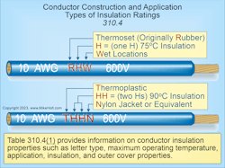
Table 310.4(1) provides information on conductor insulation properties such as letter type, maximum operating temperature, application, insulation, and outer cover properties (Fig. 1).
Conductor identification
- Insulated neutral conductors must be identified white or gray per Sec. 200.6 [Sec. 310.6(A)].
Insulated equipment grounding conductors must be identified green or green with yellow stripe per Sec. 250.119 [Sec. 310.6(B)]. - Phase conductor insulation can be any color but white [Sec. 200.6] or green [Sec. 250.119] [Sec. 310.6(C)].
Where premises wiring is supplied from more than one nominal voltage system, branch-circuit phase conductors must be identified per Sec. 210.5(C), and feeders must be identified per
Sec. 215.12(C).
Uses permitted
Conductors described in Table 310.4(1) are permitted for use in any of the wiring methods covered in
Chapter 3 and as specified in their respective tables or as permitted elsewhere in the Code. Some specifics are listed in Sec. 310.10(A) through (G). For example, conductors exposed to oils, greases, vapors, gases, fumes, liquids, or other substances (having a harmful effect on the conductor or insulation) must be a type suitable for the application [Sec. 310.10(F)].
About half of Sec. 310.10 consists of (G), which addresses conductors in parallel. Among the requirements are that the conductors must be of the same length, have the same conductor material, have the same type of insulation, and terminate in the same manner.
Dwelling services and feeders
Dwelling unit services and feeders can be sized per the following:
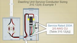
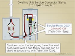
(A) Services. Service conductors supplying the entire load associated with a one-family dwelling unit can be sized per Table 310.12(A) where there is no conductor ampacity adjustment or correction as required by Sec. 310.15 [Sec. 310.12(A)]. Table 310.12(A) cannot be used to size service conductors for two-family or multifamily dwelling buildings (Fig. 2).
(B) Feeders. Feeder conductors supplying the entire load associated with a one-family dwelling or an individual dwelling unit in a two-family or multifamily dwelling can be sized per Table 310.12(A).
(C) Feeder Conductors. Not Greater Than Service Conductors. The feeder conductor ampacity for an individual dwelling unit is not required to be larger than the service conductor.
(D) Neutral Conductors. Neutral conductors can be sized smaller than the phase conductors if the requirements of Sec. 220.61 and Sec. 230.42(C) for service conductors, or the requirements of Sec. 215.2(A)(2) and Sec. 220.61 for feeder conductors are met.
Ampacities for conductors rated up to 2,000V
“Ampacity” is equal to the maximum current (in amperes) a conductor can carry continuously under its conditions of use without exceeding its temperature rating [Art. 100]. The ampacity of a conductor can be determined either by using the tables in the NEC as corrected and adjusted per Sec. 310.15, or under engineering supervision as provided in Sec. 310.14(B) [Sec. 310.14(A)(1)].
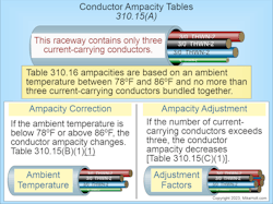
Where more than one ampacity applies to part of the circuit because of temperature correction [Table 310.15(B)(1)(1)] or adjustment factors [Table 310.15(C)(1)], the lowest ampacity value must be used for the total circuit.
Exception: When different ampacities apply to parts of a circuit because of temperature correction [Table 310.15(B)(1)(1)] or adjustment factors [Table 310.15(C)(1)], the higher ampacity can apply for the entire circuit if the length of the lower ampacity does not exceed the lesser of 10 ft or 10 percent of the total circuit’s length.
Conductors cannot be used where the operating temperature exceeds that designated for the type of insulated conductor involved [Sec. 310.14(A)(3)].
The insulation temperature rating of Table 310.4(1) insulated conductors is the maximum temperature a conductor can withstand over a prolonged period without serious degradation. The main factors to consider for conductor operating temperature are:
- Ambient temperature that may vary along the conductor length, plus from time to time [Table 310.15(B)(1)(1)].
- Heat generated internally in the conductor as a result of the load current flow.
- The rate at which heat dissipates into the ambient medium.
- Adjacent load-carrying conductors that have the effect of raising the ambient temperature and impeding heat dissipation [Table 310.15(C)(1)].
The insulation temperature rating of a conductor must be limited to an operating temperature that prevents damage to the conductor’s insulation. If the conductor carries excessive current, the I2R heating within the conductor can destroy its insulation. For this reason, elevated conductor operating temperatures created by current flow within conductors and conductor bundling might need to be limited.
Ampacity tables
The temperature ampacity correction [Sec. 310.15(B)(1)] and adjustment ampacity factors [Sec. 310.15(C)(1)] are applied to the ampacities listed in Table 310.16, based on the conductor’s insulation temperature rating.
The Table 310.16 ampacity must be corrected when the ambient temperature is not between 78°F and 86°F, and must be adjusted when more than three current-carrying conductors are bundled. The temperature correction multiplier [Sec. 310.15(B)(1)] and adjustment multiplier [Sec. 310.15(C)(1)] are applied to the conductor ampacity based on the temperature rating of the conductor insulation (not the temperature rating of the terminal) as contained in Table 310.16 (typically in the 90°C column), as shown in Fig. 3. However, the corrected or adjusted conductor ampacity must not exceed the temperature rating of the equipment terminations of
Sec. 110.14(C).
The neutral conductor might be a current-carrying conductor, but only under the conditions specified in Sec. 310.15(E). Equipment grounding conductors are never considered current-carrying [Sec. 310.15(F)].
Where raceways or cables are exposed to direct sunlight and located less than 3/4 in. above the roof, a temperature of 60°F (33°C) must be added to the outdoor ambient temperature to determine the ambient temperature correction per Table 310.15(B)(1)(1).
Ampacity adjustment
Where four or more current-carrying conductors are in a raceway or cable, the conductor ampacities in Table 310.16 in the 90°C column must be adjusted per Table 310.15(C)(1).
Where cables are bundled without maintaining spacing for more than 24 in., the conductor ampacities contained in Table 310.16 in the 90°C column must be adjusted per Table 310.15(C)(1).
The conductor ampacity adjustment of Table 310.15(C)(1) does not apply to conductors in Type AC or Type MC cable under all of the four conditions listed in Sec. 310.15(C)(1)(d). For example, the cables do not have an outer jacket.
The neutral conductor of a 3-wire, single-phase, 120V/240V system, or a 4-wire, three-phase, 120V/208V or 277V/480V wye-connected system, supplying linear loads is not considered a current-carrying conductor for the application of conductor ampacity adjustments per Table 310.15(C)(1) [Sec. 310.15(E)(1)].
The neutral conductor of a 3-wire circuit from a 4-wire, 3-phase, wye-connected system is considered a current-carrying conductor for conductor ampacity adjustments per Table 310.15(C)(1) [Sec. 310.15(E)(2)].
On a 4-wire, 3-phase, wye circuit where the major portion of the load consists of nonlinear loads, the neutral conductor is considered a current-carrying conductor for conductor ampacity adjustments per Table 310.15(C)(1) [Sec. 310.15(E)(3].
Equipment grounding and bonding conductors are not considered current-carrying for conductor ampacity adjustments per Table 310.15(C)(1) [Sec. 310.15(F)].
The ampacities of conductors in raceways, in cables, or directly buried (specified in Table 310.16) are based on the four conditions listed in Sec. 310.16. For example, there are not more than three current-carrying conductors.
Violation prevention
Correcting conductor-related violations can be expensive, due not only to the sheer work involved but also due to project completion delays. Most errors are due to incorrect use of the tables. Check the table heading to ensure you have the correct table, and carefully read the table notes.
Always choose the temperature column that matches the rating of the insulation of the particular conductor in question and doesn’t exceed the temperature rating of the equipment terminations. If you have a 90° conductor and a 60° termination, you must use the 60° column.
About the Author

Mike Holt
Mike Holt is the owner of Mike Holt Enterprises (www.MikeHolt.com), one of the largest electrical publishers in the United States. He earned a master's degree in the Business Administration Program (MBA) from the University of Miami. He earned his reputation as a National Electrical Code (NEC) expert by working his way up through the electrical trade. Formally a construction editor for two different trade publications, Mike started his career as an apprentice electrician and eventually became a master electrician, an electrical inspector, a contractor, and an educator. Mike has taught more than 1,000 classes on 30 different electrical-related subjects — ranging from alarm installations to exam preparation and voltage drop calculations. He continues to produce seminars, videos, books, and online training for the trade as well as contribute monthly Code content to EC&M magazine.