Design Guidelines for Electric Fire Pump Power Services – Part 1 of 3

- Fire pump disconnects in the same lineup as the main service disconnect and other distribution breakers.
- Fire pumps fed from the meter/main disconnect located on the opposite side of the electric utility pull section from that of the building meter/main disconnect.
- Fire pumps tapped downstream of the building main disconnect.
- Fire pumps served from alternate source generators with disconnects not grouped in vertical section(s) for emergency loads [National Electrical Code (NEC) Art. 700].
- Improper survivability applied to fire pump feeders and/or service conductors.
Setting the stage
The idea behind the electric services to fire pumps is to maintain the operation of the pump for as long as possible under the worst possible conditions. The oversizing of the normal source overcurrent protective device at lock rotor current (approximately six times the rating of the motor) is to allow the motor to continue operating even in an overcurrent and/or overheating condition without the device tripping. This is the opposite approach of what the NEC requires for any other piece of equipment in a building — where the overcurrent protective device is there to protect both the equipment and conductors.
In earlier editions of the NEC, the reason for routing the conductors outside the buildings, or concrete encased within the building, was to protect the building from possible fire caused by the overheating of the conductors. The 2023 NEC implies the reason is to protect the conductors from conditions within a building, such as a fire. However, both these conditions are met in the current NEC.
The power source(s) for electric motor-driven fire pumps
As per NEC Sec. 695.3 Power Source(s) for Electric Motor-Driven Fire Pumps, “Electric motor-driven fire pumps shall have a reliable source of power.”
I have never encountered a situation where the local inspector argued that the electric utility service was not considered reliable, but I assume it could happen. If so, you might want to consider using a diesel-driven fire pump in place of an electric-driven fire pump. The other option would require a generator as an alternate source of power to an electric fire pump with the primary source being electric utility power.
Assuming the electric utility source is reliable — and the building is not high-rise construction — the following would apply:
“NEC 695.3(A)(1) Electric Utility Service Connection. A fire pump shall be permitted to be supplied by a separate service, or from a connection located ahead of and not within the same cabinet, enclosure, vertical switchgear section, or vertical switchboard section as the service disconnecting means. The connection shall be located and arranged so as to minimize the possibility of damage by fire from within the premises and from exposing hazards. A tap ahead of the service disconnecting means shall comply with 230.82(5). The service equipment shall comply with the labeling requirements in 230.2 and the location requirements in 230.72(B).”
The above allows three different approaches for serving a fire pump. The first approach is to have the electric utility company provide a separate service lateral for the fire pump. Because it is a service lateral, the electric utility company will include a grounded neutral conductor, along with the phase conductors, requiring termination in a switchboard with a neutral disconnect link. The fire pump service entrance-rated switchboard will also include a utility meter and main disconnect device. The Code does not require the fire pump to have a disconnecting means, but most electric utility companies will. This approach would not be my first choice, as the electric utility company would generally tap the same utility transformer as the building’s permanent service to serve the fire pump, meaning two service laterals from the same source. It would also require a utility metering section and would be the most expensive of the three approaches. For an example of this approach, see Fig. 1.
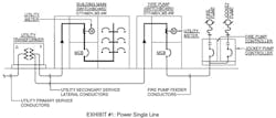
You will notice Fig. 1 includes a jockey pump, also known as a pressure maintenance pump. The purpose of the jockey pump is to maintain constant pressure in the sprinkler system piping. This ensures that if a sprinkler head is activated, the loss of pressure would be sensed at the fire pump controller, causing the fire pump to automatically start.
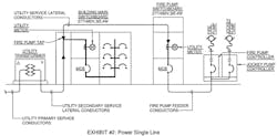
The second approach, very similar to the first, would have only one service lateral to the building and then tap the bussing in the utility pull section of the main switchboard, ahead of the utility meter and main disconnect device, for service to the fire pump switchboard. This is an extension of the service lateral, so the electric utility company would again require termination of the grounded neutral conductor and neutral disconnect link in the fire pump switchboard. The fire pump service entrance-rated switchboard would also include a utility meter and main disconnect device. Of the three approaches, this would be the second most expensive. For an example of this approach, see Fig. 2.
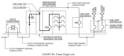
The third approach is my preferred method for fire pump services. It requires a vertical section of switchboard (nominally 18 in. wide), between the utility meter section and the main disconnect section, where the switchboard bussing is tapped to serve the fire pump disconnect. In this case, only a fire pump disconnect is required because the tap occurs downstream of the utility meter. These tapped conductors shall meet the requirements for service-entrance conductors and include the grounded neutral conductor to the fire pump disconnect, where it should be bonded to the main building ground. It is my preferred method due to the simplicity of the installation and because it is the least expensive (Fig. 3).
An earlier NEC reference mentioned there was a requirement for compliance with Sec. 230.82(5) and Sec. 230.72(B). These Code Sections read as follows:
“NEC 230.82(5) Equipment Connected to the Supply Side of Service Disconnect. Only the following equipment shall be permitted to be connected to the supply side of the service disconnecting means:
“(5) Conductors used to supply load management devices, circuits for standby power systems, fire pump equipment, and fire and sprinkler alarms, if provided with service equipment and installed in accordance with requirements for service-entrance conductors.
“NEC 230.72(B) Additional Service Disconnecting Means. The one or more additional service disconnecting means for fire pumps, emergency systems, legally required standby, or optional standby services permitted by 230.2 shall be installed remote from the one to six service disconnecting means for normal service to minimize the possibility of simultaneous interruption of supply.”
Fire pumps can be connected to the supply side of the service disconnecting means and they are also exempt from the limitation of two to six service disconnecting means.
We do not find the application for NEC Sec. 695.3(A)(2) [On-Site Power Production Facility] too often on our projects, so we have not addressed it here. In addition, NEC Sec. 695.3(A)(3) [Dedicated Feeder] is covered under Sec. 695.3(A)(1) above.
As mentioned above, where the electric utility source for an electric fire pump is determined to be unreliable, NEC Sec. 695.3(B) would apply:
“NEC 695.3(B) Multiple Sources. If reliable power cannot be obtained from a source described in 695.3(A), power shall be supplied by one of the following:
“1) Individual Sources. An approved combination of two or more of the sources from 695.3(A).
“2) Individual Source and On-site Standby Generator. An approved combination of one or more of the sources in 695.3(A) and an on-site standby generator complying with 695.3(D).”
The two options above require two sources of power for the electric fire pump, but it is the second option that would apply to most projects. This option requires an electric utility power source as the primary service, outlined above, and a generator power source, outlined under NEC Sec. 695.3(D), as the alternate service.
Unreliable power is not the only application where a standby generator is required to serve a fire pump. The International Building Code (IBC) also requires a generator for high-rise construction and further clarifies what system the fire pump falls under.
“IBC 403.4.8 Standby and emergency power. A standby power system complying with Section 2702 and Section 3003 shall be provided for the standby power loads specified in Section 403.4.8.3. An emergency power system complying with Section 2702 shall be provided for the emergency power loads specified in Section 403.4.8.4.”
The reference to Sec. 2702 above is for Emergency and Standby Power Systems and only describes the use of a stationary emergency and standby power generator system. The following identifies the fire pump as an emergency system load.
“IBC 403.4.8.4 Emergency power loads. The following are classified as emergency power loads:
- Exit signs and means of egress illumination required by Chapter 10.
- Elevator car lighting.
- Emergency voice/alarm communication system.
- Automatic fire detection systems.
- Fire alarm systems.
- Electrically powered fire pumps.
- Power and lighting for the fire command center required by Section 403.4.6.”
Where an alternate source of power is required, it shall conform with the following:
“NEC 695.3(D) On-Site Standby Generator as Alternate Source. An on-site standby generator(s) used as an alternate source of power shall comply with 695.3(D)(1) through (D)(3).”
The three items referenced below this paragraph are related to the generator capacity to accommodate the fire pump. This eliminates the requirement for tapping ahead of the generator disconnecting means and alleviates the requirement of Sec. 430.113 for disconnect means on both the utility and generator source within the fire pump room.
Where more than one source of power is provided to a fire pump, the transfer of power shall take place in the fire pump room ahead of the pump controller [NEC Sec. 695.3(F)]. This automatic transfer switch (ATS) is generally furnished as part of the fire pump controller equipment by the fire pump vendor.
Assuming the alternate source is coming from an emergency generator, the feeder shall come directly from a generator source (i.e., not passing through any other ATS). Some interpret this to mean directly from an output breaker on the generator, but my preference is to have the generator output feed directly into a generator distribution board without a breaker in the generator. This board would contain output breakers for emergency ATS(s), legally required standby ATS(s), fire pump ATS(s), and possibly optional standby ATS(s). The reasoning for not including an output breaker in the generator is two-fold: 1) The generator already contains overcurrent protection and 2) It is much harder to coordinate the overcurrent protection devices if the generator breaker is a different manufacturer than the distribution equipment. See Fig. 4 for the typical approach when two sources of power are required, and one is a standby generator.
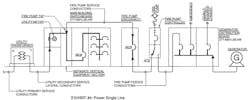
Notice the jockey pump is no longer shown when the fire pump is served from a generator. NEC Art. 695 does not address the connection requirements for jockey pumps. In previous NEC cycles, NFPA 20 included single line diagrams showing a tapped connection of the fire pump circuit, ahead of the pump controller (not within the controller) for service to the jockey pump. This is allowed by Art. 695 and is what is shown in previous exhibits within this document without generator backup. It is also shown this way in the NFPA 70, NEC Handbook. This demonstrates the importance of maintaining electrical service to the jockey pump but would not be the appropriate approach if the jockey pump requires generator backup. Tapping the electric utility fire pump feeder ahead of the fire pump ATS (ATS is furnished as part of the fire pump controller) for service to the jockey pump would not ensure jockey pump operation during a power outage.
The NEC does not allow the tapping of the jockey pump feeder between the ATS and the fire pump controller. If the operation of the jockey pump is critical to the fire pump operation, it should also be backed up on the generator. The only viable option left is to service the jockey pump from the emergency branch distribution system, as the fire pump and accessory loads are considered part of the emergency systems covered under NEC Art. 700.
If you have a building (not high-rise construction) with an electric fire pump that includes an emergency generator, but the electric utility source is considered reliable, you might give the owner the option of supplying the fire pump with an alternate generator feed, although not required by the Code. It is sometimes difficult to explain to an insurance carrier why the most critical part of a life safety system was not backed up when there was a generator on the project.
This wraps up Part 1 of this three-part series on electric fire pump power services. Look for Part 2, which will address the continuity of power requirement in the NEC, and Part 3, which will dive further into specific wiring requirement and applications, online and in print.
**Reproduced with edits and permission of NFPA from NFPA 70*, National Electrical Code, 2017 edition. Copyright© 2016, National Fire Protection Association. For a full copy of the NFPA 70, please go to www.nfpa.org.
About the Author

Brian E. Smith
Brian has spent 48-years of his career with the electrical engineering consulting firm of The Engineering Enterprise, a California based company, where he served as one of the principals for the past 38-years and as president for 20 of those years. He has over 100 million square feet of design experience for a large variety of project types that include low- and high-rise construction, office campus projects, medical office buildings, labs, multi-family residential, universities, primary K-12 schools, and parking structures. His special interests are in Codes and Standards, as well as being the author of the company’s master specification. He can be reached at [email protected].