Ground-Fault Protection and the Multi-Wire Branch Circuit: A Troubled Marriage


Ground-fault protection and the multi-wire branch circuit (MWBC) are both common topics in the electrical industry. This article discusses their union — the use of a 2-pole GFCI/GFPE breaker to protect the two 120V legs (L1 and L2) of a 120V/240V split-phase, 3-wire (L1/L2/N), shared neutral circuit. You may be surprised (as I was) to find that the protection provided is attended with subtle (if not troublesome and problematic) differences from the protection provided by a single-pole breaker on a 2-wire circuit (hot/neutral). The manifestation of these differences in a marine environment is of particular interest and will be highlighted in this piece.
Several years ago, I began thinking about the effects of marina basin background current (sometimes called foreign or stray current) on the measurement of AC leakage from boats — as is commonly made by clamping the shore power cord with an ammeter. I concluded that the effect of background current depends on whether it originates from the same or opposite leg (L1/L2) of the distribution source as the current leaking from the boat circuit.
That led to the question of how fault/leaks from different legs of a main or feeder panel would be seen by a 2-pole (L1/L2/N) ground-fault protection breaker. So far, I have been unable to locate a treatment of this subject. (Perhaps readers will be able to provide me with references.) So based on my analysis, simulation, and testing as well as interaction with a few electrical professionals, I have reached preliminary conclusions. They are presented in this article with the expectation that they will elicit comments, critique, and reader feedback from the EC&M audience.
The GFCI current transformer
Before considering the 2-pole ground-fault protection breaker on an MWBC, let’s look briefly at the single-pole, 2-wire (H/N), GFCI/GFPE breaker (Fig. 1). Its heart is the residual current transformer (CT). The core of the transformer is typically a toroid — a doughnut-shaped ring of magnetic material (the heavy black ring in Fig. 1). Both the hot and neutral conductors are passed through the toroid, making each of these conductors a single-turn primary winding of the CT.
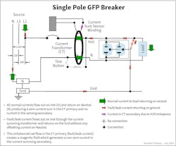
The transformer’s secondary is a multi-turn winding on the toroid that functions as a sensor. It is energized when the sum of the currents in the hot and neutral primaries is non-zero. Consider current flowing through the toroid on the hot or neutral from the source toward the load to have one sign (+ or -) and current flowing in the other direction to have the opposite sign (- or +, respectively). If the current that flows from the source out on the hot wire is equal to that returning through the neutral, then a net-zero primary current results — so no magnetic field is generated; therefore, no current flows in the secondary winding. This is the case when the circuit has no leaks or faults to ground.
When things don’t add up
On the other hand, if some of the current returns to the source — not on the neutral but on the safety ground or through some environmental path — (e.g., a person, a building structure, and the earth), then there is a current imbalance. The neutral return current will be less than the hot supply current. These unequal, opposite direction hot and neutral currents do not offset each other. The result is a non-zero net current through the primary windings that produces a magnetic field whose AC dynamics induce a current in the sensing secondary winding — a current that is proportional to the imbalanced current sum. If the imbalance reaches the trip level for the breaker (e.g., 5mA for a GFCI and 20, 30, or 100mA for a GFPE), then the breaker is tripped by processing circuitry, which opens the hot conductor path.
To be able to periodically test its functionality, a GFCI/GFPE breaker is equipped with a manual test circuit. A push-button switch completes a path from the load side hot through a resistor to the supply side neutral, thereby providing a return path for a test current that does not flow through the toroid. The imbalance created simulates an actual fault or leak. Since the resistor is chosen so that the current is just above the trip limit, the breaker trips in the usual way. Typically, this test is to be performed monthly.
An additional conductor
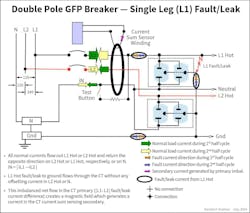
Now let’s consider the subject circuit: a 120V/240V multi-wire branch protected by a 2-pole (L1/L2/N) GFCI/GFPE breaker (Fig. 2). A second ungrounded conductor (red in Fig. 2) is added to the single-pole breaker current transformer as a third primary. This conductor originates on the opposite leg (line or split-phase) of the single-phase service source. It takes a switched path through the breaker and passes through the CT toroid to a load-side connector. From there, it is wired to a separate 120V circuit (L2), but it uses the same neutral as a return path. Normal load current flows out L1 hot or L2 hot to the load and returns on L2 hot or L1 hot, respectively, or on the neutral. The current on the neutral is the difference between the L1 and L2 currents [iN = | iL1 – iL2 |]. An L1 fault or leak to ground (red zigzag in Fig. 2) flows through the current summing transformer (on L1) without any offsetting current in L2 or N. Just as in the single-pole breaker, this imbalanced net flow in the primaries creates a magnetic field that generates a non-zero current in the current summing secondary, and the breaker trips at the designed trip current level.
Ground: where opposite faults meet
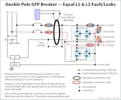
That explains the case of a fault/leak on one leg (L1) or the other (L2). But suppose there are fault/leaks on both the L1 and the L2 120V branch circuits. First, consider the case of equal fault/leaks (Fig. 3).
The current flow for equal fault/leaks is similar to that of equal loads (L1 and L2) — the return current for each uses the opposite leg. Follow the L1 fault/leak current (orange arrow in Fig. 3) from the L1 source through the CT out to the L1 leg fault. It flows to ground through the L1 fault path and then through the L2 fault to L2 and returns on L2 through the CT to the source. So no current returns on the ground or the neutral. The current that flows from L1 returns in L2 and vice versa. The current sum in the CT primaries is zero; therefore, there is no magnetic field, no current in the secondary, and no trip. Note that regardless of the size of the fault/leaks, if they are equal, the breaker will not trip.
A more likely case
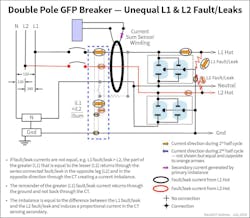
But suppose one leak is smaller than the other (Fig. 4). Let’s say the 2-pole breaker is a GFPE with a 30mA trip limit. Suppose the appliances connected to L1 have a total fault/leak current of 25mA, and the L2 total is 15mA.
Normal currents (not fault/leaks) flow to and from the load on the L1/L2/N as usual; therefore they will flow in equal amounts in both directions through the CT and will not contribute to any current imbalance measured by the secondary. They are being ignored in this analysis.
Let's trace the fault/leak currents on the positive AC half-cycle (i.e., when the instantaneous L1 voltage is greater than the L2 voltage. See the orange arrows in Fig. 4). The L1 current, 25mA, travels from the source through the CT to the fault/leaks and then through them to ground. At the ground point, 15mA of the 25mA travels through the L2 fault/leakage path to the L2 circuit and returns through the CT to the source on the L2 circuit. The remaining 10mA follows the ground path back to the source via the panel ground to neutral bus connection. During the negative half-cycle, the currents all reverse on the same paths and in the same amounts. (The negative half-cycle is not shown in Fig. 4; they would be blue arrows equal in size and head to head with each orange arrow.)
The current imbalance in the CT primaries is: 25mA L1 source to load (+), 15mA L2 load to source (-) and 0mA through the neutral, 25mA + (-15 mA) + 0 = 10mA. The resulting magnetic field induces a current in the secondary indicative of a 10mA imbalance so the breaker will not trip (10mA < the trip level of 30mA).
A fault/leak above the trip limit
Let’s look at another case. With L1 still faulting/leaking at 25mA, suppose L2 gets an additional 35mA fault (5mA over the 30mA trip limit) — bringing its total fault/leak to 50mA (15mA + 35mA). Using an analysis similar to the above, we can trace the fault/leak currents but use the negative AC half-cycle this time. The 50mA L2 current flows from the source on L2 through the CT toward the load but takes a fault path to ground. From there, it splits — 25mA takes the L1 fault/leakage path to the L1 circuit and returns through the CT on the L1 conductor. The remaining 25mA returns through the ground to the neutral bar in the panel. With a 50mA source to load on L2 and a 25mA load to source on L1, the CT imbalance is 25mA detected by the secondary. But that is still 5mA short of the required 30mA to trip. So with 75mA flowing through faulting/leaking paths, 25mA on L1, and 50mA on L2, the 30mA breaker still will not trip.
This can’t be right
Looking closer, there’s still more confusion. Suppose that 20mA of the 25mA L1 fault/leak is due to a fault in a single appliance. If this faulty appliance is removed, the L1 fault/leakage drops to 5mA, the imbalance increases to 45mA (50mA L2 – 5mA L1 = 45mA > 30mA), and the breaker trips.
If we reconnect the faulting appliance and reset the breaker, it does not trip because the imbalance goes back down to 25mA.
Failure of push to test
One of the most troublesome and unhelpful consequences of 2-pole ground-fault protection of an MWBC is the effect on the push-to-test feature (Fig. 5). As described earlier, the test button produces a current imbalance just above the trip limit. Let’s suppose in the case of our 30mA trip example GFPE, the test circuit draws 31mA from L1 (shown in Fig. 5 by large orange arrows circled in black).
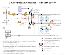
Provided there is no leak or fault on L2, the breaker will trip when the test button is pressed since the entire 31mA will be an imbalance. But if there is a leak or fault on L2 (shown in Fig. 5 by mid-sized orange arrows circled in red), a portion of the test current flows through the neutral-ground connection in the panel, through the L2 fault/leak and onto the load side of L2, and then back through the CT to the source, thus reducing the 31mA imbalance by the amount of the L2 leak. If the L2 leak is more than 1 or 2mA, the test button imbalance will not be enough to trip the breaker (31mA - 2mA < 30mA). Unless L2 is essentially free of fault/leaks, the push to test button will misidentify a good breaker as faulty.
Let’s return to our continuing example and actuate the test button. After reconnecting the faulting appliance, L1 has 25mA of fault/leak current and L2 has 50mA. If the test button is pushed, ~31mA is added to the 25mA L1 leakage path, bringing the L1 total fault/leak up to 56mA. With L2 fault/leak current at 50mA, there is a 6mA imbalance, 56mA + (- 50mA) + 0mA = 6mA, which is less than the trip limit. The breaker does not trip, thus indicating a bad breaker. A good breaker fails the push button test.
Let’s call the doctor
Note how difficult this circuit would be to diagnose. If all appliances were removed, the breaker would test “good.” Then, as the devices are reconnected, the point at which the breaker would test bad, or trip (even if it would trip at all) would depend on the order of reconnection. If L2 were disconnected or all L2 loads removed (only L1 connected, 25mA fault/leak current), the breaker would not trip, and the test button would trip the breaker. If L1 were disconnected from the breaker or all L1 loads removed (only L2 connected, 50mA fault/leak current), the L2 fault/leaks themselves would trip the breaker. We could multiply similar examples of unnecessary confusion when trying to track down problems — confusion that would not exist if 120V circuits requiring ground-fault protection were provided their own neutral return rather than sharing a neutral with another circuit on a multi-wire branch. Before dismissing this musical connections scenario as unlikely, consider the marina where connecting and disconnecting boat shore power with varying and uncertain order is the norm.
Bottom line effects
In a nutshell, what we find is that when feeding an MWBC, the 2-pole ground-fault protection breaker trips when the imbalance caused by the difference in the L1 vs. L2 fault/leaks exceeds the trip limit. In other words, it trips when:
│(L1 leaks & faults) – (L2 leaks & faults) │> Trip Limit.
It is incapable of tripping on an L1 fault at the trip limit unless the leakage and fault current of L2 is equal to or less than that of the pre-fault L1 circuit. For the faults or leaks on one leg (L1) to cause a trip, they must exceed the total faults and leaks on the other leg (L2) by at least the trip limit.
To put it another way, the common multi-wire branch circuit cannot be protected against ground faults to the same degree and with the same precision, the same measures of protection, consistency, and expectation of behavior, etc., as a branch with its own neutral. This is not all that surprising when you consider that by sharing a neutral, the return current of each branch is made anonymous as to its origin (L1 vs. L2).
- Fault current on one leg above the rated ground-fault protection level is required to trip the breaker in the presence of a fault/leakage current on the other leg, thus decreasing fault detection sensitivity.
- The manual test button will not reliably perform a valid test. A good breaker will test bad when L2 fault/leakage current is greater than that of L1 (plus test current margin) or when L1 fault/leakage current is greater than that of L2 (plus margin), depending on whether or not the current for the test button is drawn from L1 or L2, respectively.
- L1 and L2 circuits may be able to sustain leakage/fault currents well above the rated ground fault protection level. That is, fault/leaks may be arbitrarily high without tripping the breaker so long as their fault/leakage difference (L1 vs. L2) is less than the rated ground-fault protection level. For example, a faulty/leaky boat, which trips the feeder’s 2-pole GFCI/GFPE when connected to an L1 120V/30A circuit, could work just fine without tripping if moved to an adjacent L2-powered receptacle. If, when moved to L2, the L2 fault/leaks are now greater than those of L1, then the fault/leaks of the next boat to connect to an L2-powered receptacle could cause a trip. But likewise, it could then be moved to L1, and so on. So long as the difference in fault/leaks between L1 and L2 remains below the trip limit, faulty/leaky boats could continue to be added, increasing the total fault/leakage current flowing through the GFPE device into the water.
- The removal of an appliance or device from a circuit could cause a trip. This happens when the fault/leak in the removed device is of such value that, when removed, it increases the L1 vs. L2 difference up to the trip level. The order of appliance connection and disconnection determines the possible, trip/non-trip, circuit states.
What circuits are affected
These effects apply to virtually every 120V multi-wire branch that consists of a grounded neutral conductor and two ungrounded conductors from opposite legs (L1 and L2) of the 240V split-phase source. However, the implications in some cases are decidedly more significant than in others.
On the less troublesome end of the spectrum might be the dishwasher and garbage disposal split duplex receptacle that is fed by a 2-pole Type A GFCI breaker (where permitted by applicable codes). In the first place, the Class A GFCI trip point is low (~5mA), so the test button dead zone (where good breakers will test bad) for a test current of 7mA would be only about 3mA wide (i.e., for fault/leak differences of greater than about 2mA and less than 5mA). Also, there is only one appliance connected to either leg (L1/L2), there are no available additional receptacles, and the two that do exist are typically not conveniently accessible to be subject to change. Lastly, but perhaps most importantly, both the wiring and the appliances are subject to mandatory standards and codes.
At the more troublesome end might be a 2-pole (L1/L2/N) 100mA GFPE multi-wire branch circuit at a marina that supplies 120V/240V as well as both L1 and L2 120V to shore power pedestals which could contain 2-pole 30mA GFPE feeding 120V/240V shore power receptacles. The circuits’ connected loads (i.e., the boats) vary widely both as to the mix of appliances and devices onboard and also with time (here today, gone tonight, in a different slip tomorrow) and are not subject to mandatory codes. In addition, the circuit fault/leaks could exceed a safe limit and could be flowing through persons or animals in the water.
Other devices
GFCI/GFPE breakers are the focus of this article, but what other devices might be subject to some of these same effects when used on shared neutral circuits (L1/L2/N)? Any of the alphabet soup of residual current devices (RCDs) that provide ground-fault protection is suspect.
For example, the ELCI used onboard boats that is called for in the American Boat and Yacht Council (ABYC) E-11 standard is another ground-fault protection device that uses residual current detection. Those that provide 3-wire 120V/240V (L1/L2/N) multi-wire branch protection are subject to these same issues.
What about the arc fault circuit interrupter (AFCI)? If some AFCI breakers use residual detection as a component of its functionality, then perhaps a 2-pole (L1/L2/N) AFCI feeding a multi-wire branch circuit could be subject to some of the same problematic behaviors as are GFCI/GFPE devices depending on its implementation. This needs further study.
What now?
Each of us operates in our own sphere of activity and influence, whether that be standards and code-making, engineering, construction, maintenance, or property owner. We should all look for ways to combat the confusion and problems of the GFCI/GFPE-MWBC union. Some ways in which we can do this might include:
- Advance the awareness and understanding of this behavior in forums, presentations, publications, and continuing education.
- Consider limiting the use of a 2-pole GFP device on an MWBC for ground-fault protection of 120V circuits to small, well defined, or stable circuits with small numbers of appliances and few, if any, open receptacles (sockets), such as for garbage disposals and dishwashers using a split duplex receptacle.
- Minimize their use at docks, marinas, boathouses, and aboard boats. Where permitted and feasible at docks and marinas, provide ground-fault protected 120V L1 and L2 feeder circuits to carry 120V service to the pedestal rather than drawing it from a 120/240V MWBC circuit in or near the pedestal. By doing this, the only circuits subject to the limitations of the 2-pole GFP device will be those boats that connect to 120V/240V shore cords.
- Aboard boats, provide single-pole GFP devices to protect 120V circuits that are supplied by a 120/240V shore cord — even those connected through an ELCI (L1/L2/N/).
- Most ill effects of offsetting fault/leaks may be substantially reduced by feeding L1 and L2 with two phases of 3-phase 208Y/120V service. Any two phases differ by 120 degrees, whereas the two legs of 240/120V split-phase service, the subject of this article, are directly opposed (differ by 180 degrees). It can be shown that an L1 to ground fault/leak will only increase the L2 fault/leak current required to trip by at most about 15%. For example, a GFPE with a nominal 100mA trip limit would require at most about 115mA (nominal) to trip in the presence of an existing fault on the other leg. For environments such as boatyards and marinas where fault/leaks are likely and are especially dangerous, this advantage of 208Y/120V service should be considered.
About the Author
Randal Andress
Randal Andress holds a B.S. in Electrical Engineering and is retired from Northrop Grumman. He is a Vietnam era veteran (USAF) and is a member of NFPA and the Electric Shock Drowning Prevention Association. He can be reached at [email protected].