Performing electrical cable heating calculations can be a cumbersome task, but they’re essential to accurately determining the allowable ampacity of an underground electrical duct bank installation. Improper heating calculations can lead to an undersized duct bank, which can be a costly mistake to fix — if it’s even possible. Electrical engineers designing electrical duct banks must understand the soil’s thermal properties and the effects it will have on the overall installation. In order to properly size the duct bank, the following factors must be considered and evaluated:
• Heating effects of the cable
• Heating effects caused by the surrounding soil
• Ampacity calculation equations
• Engineering solutions
Heating effects of the cable
As the cables in the duct bank transmit current, heat is generated due to losses in the cable. All cables have a temperature threshold that must not be exceeded for extended periods of times, or physical deterioration of the cable will begin — increasing the possibility of a fault occurring. Common practice for large underground duct bank cables is to utilize the 90°C rating.
The temperature rise of the cable is generated from the current producing (I2R) losses through the cable’s conductor, sheath, and conduit as well as the temperature rise produced from the cable’s dielectric losses. Heat created by dielectric losses is due to the energy needed for the electrons to overcome the opposition of the electromagnetic field’s alternating polarities. In low-voltage applications, the temperature rise due to dielectric losses is relatively small compared to the overall temperature rise of the cable. However, these must be taken into account in high-voltage applications.
Most electrical duct bank installations will contain more than just one cable. Each cable in the duct bank will generate its own source of heat and conduct this heat to the other cables. This is referred to as mutual heating.
The effects of mutual heating between the cables are dependent upon the spacing between each of the cables and the symmetry in which the cables are arranged. Mutual heating effects can also occur between two duct banks installed close to each other. In reality, any heat-producing object within close proximity of the duct bank will transfer heat in the duct bank system and further de-rate the ampacity of the cabling system.
Heating effects caused by the surrounding soil
The thermal properties of the soil in which the duct bank is installed are the most critical aspect to the design. As the cables generate heat, it is dissipated to the surrounding soil and concrete encasement materials. Conduction of heat from the cables to the surrounding materials occurs due to temperature differences between materials. If there is a temperature difference between two systems, heat will transfer from the hotter system to the colder system until the system reaches a point of thermal equilibrium. For underground duct banks, the primary means of heat transfer is through conduction. Convection takes part in the air space between the cables and the conduits in the duct bank, but the heating effects due to this method of heat transfer is minimal in comparison to the heat transferred through conduction. The relationship between heat flow and the resulting temperature gradient can be represented by Fourier’s Law of thermal conduction:
Q = -kVT
Where:
Q = Local heat flux density (W/m2)
k = Thermal conductivity of the material (W/m-K)
VT = Temperature gradient, (K/m)
What Fourier’s Law states is that a temperature change in the surrounding material will only occur if there is a gradient in the heat flow. How effectively the heat distributes through the soil and away from the cables is determined by the thermal conductivity of the soil. As the thermal conductivity of the soil decreases, the temperature gradient increases. This causes an increase of temperature to the surrounding soil, further de-rating the ampacity of the cable.
Thermal conductivity of soil is dependent on two factors: the soil’s density and water content. Increasing soil density will provide more physical contact between the solid particles of the soil, allowing better thermal conductivity. Increasing the water content of the soil will also provide more physical contact between the solid particles of the soil and replace the air in the soil with water. Water has a much higher thermal conductivity than air, which is why moist soils will provide enhanced thermal conductivity.
Moist soils also have higher heat capacities than dry soils, meaning it takes more heat energy to raise the soil’s temperature. The water content of the soil can potentially be reduced as the heat generated from the cables is conducted to the surrounding soil. In other words, the soil can dry out as a result.
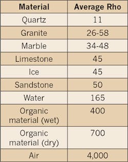
Typically, soil’s thermal properties are expressed in terms of thermal resistivity (which is the inverse of thermal conductivity) — better known as its Rho value. For electrical duct banks, lower values of Rho are desired for the surrounding soil and concrete encasement materials. Lower Rho values allow the heat generated from the cables to dissipate farther away. This results in lower changes in temperature throughout the soil. Soils with higher Rho values will not dissipate the generated heat as effectively and will insulate the cables, causing the heat energy to build up closer to the cables and reduce their allowable operating ampacity. If the surrounding soil is especially dry (or susceptible to drying out quickly), the possibility of a “thermal runaway” increases, resulting in worst-case soil conditions. Refer to the Table for a reference to the average Rho values of various materials.
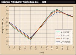
Another factor that affects the duct bank design is the ambient temperature of the surrounding soil. There are daily (diurnal) cycles as well as seasonal cycles for the ambient temperature variations in the soil. These cycles are in response to the fluctuating inputs of solar radiation due to the sun. The magnitude of these temperature cycles decrease with depth due to the reduction of radiated heat energy as it travels through the soil. Typically, the depth at which the soil remains at a constant temperature throughout the day is beyond the depth at which an electrical duct bank would be installed. As expected, the average ambient temperature of the soil will be lower during the winter than the average ambient temperature of the soil during the summer. Refer to Fig. 1 for a reference of how the average daily temperature of the soil varies throughout the year at different depths. When designing large electrical duct banks, the annual worst case ambient temperature of the soil should be considered.
Ampacity calculation equations
One common method of estimating the steady-state temperature of the duct bank cables is using the Neher-McGrath calculation method. The Neher-McGrath equation estimates the temperature rise of cable systems in steady-state conditions by constructing a thermal circuit equation using thermal equivalents of the cable. The maximum temperature rise of the cable is calculated based on the maximum load for the cable system under a repeated daily load cycle. The equation also assumes the surface of the earth acts as a thermal reservoir in which its heat capacity is large enough to remain at a constant temperature.
As shown in the Neher-McGrath Equation, the cable’s allowable ampacity will decrease as both the ambient temperature and resistivity (Rho value) of the soil increase. The Rho value of the soil is included in the Rca’ term, which is also affected by the depth of the duct bank, indicating that the allowable ampacity of the cable will decrease as the depth of the duct bank increases.
Another common method of estimating the steady-state temperature of the duct bank cables is using the IEC 60287 calculation method. The IEC 60287 Standard, “Calculation of the Continuous Current Rating of Cables (100% Load Factor),” is another commonly used method for calculating the allowable ampacity of a cable for applications up to 5kV. Like the Neher-McGrath equation, the IEC equation estimates the temperature rise of cable systems in steady-state conditions based on the heat generating losses within a cable. Both the Neher-McGrath and the IEC calculation methods use a two-dimensional analysis to calculate the steady-state temperature of underground cables.
Both calculation methods yield similar results for steady-state conditions. A two-dimensional analysis can be assumed because the ratio of the cable length to the cable diameter is very large. Even though these equations are considered as simplified calculations for determining an underground cable’s ampacity, both are still very complicated to perform by hand. For this reason, software packages are commonly used for underground cable ampacity calculations.
Engineering solutions
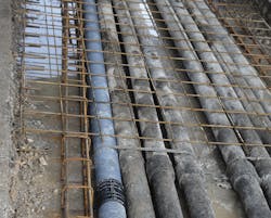
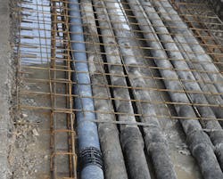
When designing large underground electrical duct banks (Fig. 2), the following topics should be explored and evaluated to determine their relevance to the design.
• Select an engineered low Rho backfill as opposed to using the native soil. This method will often provide better soil conditions for conducting heat and will eliminate any approximations of the existing soil. If providing a low Rho backfill is not an economical solution, in-situ soil testing should be performed. The results of the soil testing should provide information of the soil’s Rho value with respect to the amount of water content.
• Consider using a low Rho concrete mix for the duct bank encasement.
• Does the application require the assumption of a 100% load factor? Applications such as data centers and other mission-critical facilities require an assumption of a 100% load factor. However, this might not be the case if the installation is for a typical commercial building application.
• Are 90°C rated cables terminating to equipment with 75°C rated terminations? If so, the de-rated ampacity of the 90°C cables must not exceed the base ampacity of the same size cable rated for 75°C.
• Are there any other nearby heating elements, such as a steam pipe or another duct bank system, that need to be considered in the heating calculations? These additional heating elements can be accurately modeled if a high-end software program is being used for the calculations.
• Is the neutral wire being provided? If so, the allowable ampacity of the cables will need to be de-rated appropriately per NEC.
Conclusion
Every duct bank installation requires a unique solution that fits the project at hand. Not considering the heating effects associated with the cables and surrounding environment will lead to an undersized duct bank installation, and limit the reliability and performance of the entire system.
Jones is an electrical designer in CallisonRTKL’s Baltimore office. He holds an EIT certificate and is a LEED green associate. He can be reached at [email protected].
SIDEBAR 1: Neher-McGrath Equation
I = √[(Tc – (Ta + ∆Td)] ÷ [Rdc × (1 + Yc) × Rca’)]
Where:
I = ampacity (kA)
Tc = conductor temperature (°C)
Ta = earth temperature (°C)
∆Td = conductor temperature rise due to dielectric loss (°C)
Rdc = conductor DC resistance (µΩ/ft)
Yc = loss increment due to conductor skin and proximity effects (P.U.)
Rca’ = thermal resistance between conductor and ambient earth (thermal Ω-ft)
SIDEBAR 2: Basic Definitions
Ampacity — The ampacity of a conductor is its current-carrying capacity. It is defined as the amount of current the conductor can transmit before deterioration or damage begins to occur.
Heat and temperature — While heat and temperature are related to each other, heat is the total energy of molecular motion in a substance while temperature is a measure of the average energy of molecular motion in a substance. All substances have their own heat capacity that relates to the amount of energy (heat) needed to be added in order to raise its temperature. The heat capacity of a substance depends on the type and amount of material.
Conduction — The transfer of heat between substances that are in direct contact with each other by means of molecular agitation without any motion of the material as a whole. As the object is heated, the molecules will gain more energy and vibrate more. This energy is transferred between molecules as they bump into each other. The better the conductor, the faster the heat will be transferred.
Convection — The transfer of energy from hot places to cold places by a fluid (liquid or gas). As the heated fluid moves away from the source of the heat, the fluid carries energy away with it and is replaced with the cooler liquid.
Radiation — The transfer of heat that does not rely on direct contact between objects and can be transferred through empty space without a medium and the exchange of mass.
Rho value — The Rho value is the thermal resistivity of a substance expressed in units of °C-cm/W. Thermal resistivity is the reciprocal of thermal conductivity and refers to a material’s ability to transfer heat through conduction. Thermal resistivity is not the same as thermal resistance; thermal resistance is dependent upon the resistivity and geometry of the material where thermal resistivity is not.
Load factor — Load factor is defined as the average load divided by the peak load in a specified period of time — typically over 24 hours.


