Have you ever had difficulty explaining the theory of inductance and its impact on an electrical circuit to a coworker or apprentice? A theoretical topic such as this is hard to comprehend but essential to understanding the operation of many types of electrical equipment. So how do you get your points across in the most effective manner? Some things are easier to show than they are to explain.
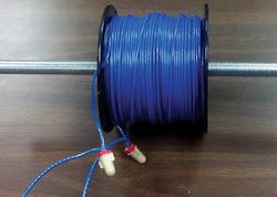
One way of showing the effects of inductance (and inductive reactance) on a circuit is to demonstrate its effects. A quick demonstration may include something as simple as a spool of 12 AWG wire.
If a voltage is applied across 500 ft of wire on a spool, most novices expect a high amount of current to be flowing in this circuit, thus causing an overcurrent protective device to activate. This would be a logical assumption, but it’s not true. The effects of inductance and inductive reactance have a substantial impact on the current in this arrangement.
If we take a closer look at the parameters of the circuit that’s created, we see that based on Chapter 9, Table 8 of the 2014 NEC, the resistance of 12 AWG copper conductor is 1.93 ohms per 1,000 ft. Using Ohm’s Law (I = E ÷ R), we divide 120V by 0.965 ohms (½ of 1.93 ohms), which results in 124A in the circuit. This is obviously more than enough to cause a 20A overcurrent protective device to open.
What actually happens when 120V is applied to a spool of wire? There really is no noticeable change that occurs with this arrangement. But how could this be?
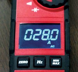
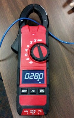
When we measure the current flowing through the wire, we see it’s 28A (Photo 1). This result is far lower than the one expected using the Ohm’s Law formula. Because the voltage and resistance of the wire are known values, you can deduce there must be more than just voltage and resistance at work in this circuit. In this case, the resistance (actually the impedance) of the circuit had to be something more than 0.965 ohms. In effect, the resistance (impedance) can be found by simply rearranging the formula to solve for Z (Z = E ÷ I). In this case, take 120V and divide it by 28A, which would result in 4.28 ohms of impedance. At this point, it should be clear that the wire being coiled onto the spool has had some effect on the circuit parameters.
To further illustrate the effects of inductance and permeability of the inductor core, we could slide a piece of conduit through the center of the spool of wire (Photo 2.) The result is a further decrease in the amount of current in the circuit as a result of the decreased inductive reactance created by the iron core.
This simple experiment should serve as the start of a better understanding of inductance, inductive reactance, and its effects.
Riesberg is director of curriculum development for the National Joint Apprenticeship and Training Committee (NJATC) in Upper Marlboro, Md. He can be reached at [email protected].


