Arc Flash Hazard Evaluation
If you’re conducting an arc flash study, you’re probably using one of the many software packages that can perform the analysis for you — at the click of a button. However, as convenient as they may seem, there are several pitfalls that can cause erroneous results if you are unaware of the underlying premises behind many of the calculations. The following five considerations are important issues to keep in mind when you’re doing this type of work.
Source Impedance
Fault current sources like power generators cannot supply faults in a power system indefinitely. The fault current magnitude is, in fact, limited by the generator’s internal reactance, transmission line impedance, transformer impedance, and series reactors (when present). You can model the source either without these impedances (infinite source) or with these impedances. When undertaking a study for a large commercial or industrial site, assuming an infinite source for the electrical model is a big “no no.”
When you have the source impedance, make sure you understand at what point it is calculated. Typically, you would want it calculated up to your facility’s service entrance location. If there is a transformer at the facility service entrance, make sure you know whether the electric utility has provided source impedance data to the high side or low side of the transformer.
System impedance at the facility’s service entrance is not always readily available. Approaching the electric utility early on, especially while scoping the project to obtain this piece of information, is necessary. When this is not feasible, the scope of work should at the very least insist on obtaining this data from the electric utility.
Incorrectly modeling the source impedance has a huge impact on the study, so make sure you have the most up-to-date and correct source information before making any calculations.
Transformer Grounding
During the data collection process, it is easy to miss out on how the neutral of a transformer is grounded. You could have a solidly grounded, low-resistance grounded, high-resistance grounded, or an ungrounded system. You can make reasonable assumptions on other transformer parameters, but you cannot make an assumption on how it is grounded.
How does this affect the study? Solidly grounding the transformer provides high fault currents on its secondary side. This leads to faster protective device trip times, which results in lower incident energy at the fault. Low-resistance grounding provides much lower fault currents on the secondary, which leads to slower trip times and higher incident energy at the fault. High-resistance grounding schemes provide extremely low fault currents and do not trip for the first ground fault. Ungrounded systems also will not trip for the first fault to ground. Timing of ground fault tripping in high-resistance and ungrounded systems may depend upon the activation and timing of phase protective devices that are not as sensitive and quick to operate as a ground protective device on a solidly grounded system.
IEEE 1584 or NESC Art. 410?
Sometimes, the scope of work for an arc flash study extends beyond the indoor distribution substations to outdoor air-insulated substations or distribution lines. This raises an interesting question. Would you still apply the IEEE 1584 standard in these areas? Probably not, for the following reason: The IEEE 1584 equations were empirically derived for systems rated between 208V to 15kV with live conductor distance ranging from 13 mm to 152 mm. Arcing due to a single-phase fault in such a setup will easily flashover to the other two phases and create a full 3-phase fault. However, how often do you see a single-phase fault escalate to a 3-phase fault in a substation? Not often. Most faults are cleared within a few cycles of fault initiation. In such a scenario, using the single line-to-ground fault current to calculate the arc flash incident energy is more meaningful than using the 3-phase bolted fault current (which IEEE 1584 employs).
Thus, extrapolating a solution for an outdoor arc flash in substations or on lines rated 34.5kV or 69kV using the IEEE 1584 standard is not realistic. It will, at best, generate a conservative solution with unreasonably large working distances, such as 30 ft or more, and a requirement for higher class personal protective equipment (PPE) that limits the dexterity of a worker.
There are very few software packages in the industry that can model single-phase arcs for the purpose of determining incident energy in substations. Common practice for the utility is to follow the IEEE’s National Electrical Safety Code (NESC) C2 standard. The tables in NESC Art. 410 allow for the determination of appropriate PPE based on the premise that faults are single-phase and take place between open air live-line to earth. However, to use the tables, you must know the number of cycles the upstream breaker takes (including relay operation time) to clear the fault and the available fault current in the system at the location of the fault.
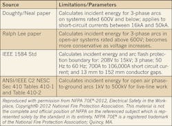
Choosing the right standard for the arc flash study is just as important as proper data collection. There are several methods you can follow; however, ones that are normally used (besides NFPA 70E) are listed in the Table below. NFPA 70E and IEEE 1584 standards are implemented in low-voltage to medium-voltage enclosed systems, while NESC Tables are used for high-voltage open-air systems.
Bolted Fault Current vs. Arcing Fault Current
These two fault currents are not the same in systems rated less than 1,000V. By definition, a bolted fault has no fault impedance while the arcing fault current has impedance associated with the arc. The bolted fault, therefore, has higher fault current magnitude than the arcing fault. The protective devices in the low-voltage systems are coordinated to trip for the higher bolted fault current and not the arcing fault current.
Because protective device clearing time is an important factor in the calculation of incident energy, you must understand that it’s the trip time to clear the arcing current that’s used in the calculations — not the delay time (if any) you may have programmed into the protective device for clearing of a bolted fault.
Programming relays for faster trip times based on arcing current sacrifices relay coordination and may put a large portion of the system out of service under fault. But if safety is paramount, then reducing the delay time in circuit breaker operation, by any means, is necessary.
Circuit Impedance
As implied so far in this article, fault current magnitude and trip time significantly affect the incident energy in an arc flash. The available fault current in a system is a result of the way the power system network is configured and the way the power system components are connected. For example, if you have multiple transformers feeding a bus duct, the available fault current at the bus duct will increase significantly. This is due to the reduction in circuit impedance when the transformers are paralleled. Additionally, if an on-site co-generation unit is operated only during certain times of the day or month or year, then its fault contribution needs to be considered as well.
Make sure you understand how the electrical system is configured. Changes in circuit impedance can affect the fault current and thereby the incident energy. A complete understanding of the system is critical to providing an appropriate flash hazard evaluation.
The five items mentioned in this article are a few of the important parameters that require engineering expertise in establishing the basis for an arc flash hazard study. However, there are other significant considerations that must be evaluated, some of which are dependent upon the specific site conditions, switchgear or panelboard construction, and project scope. That’s why it’s important to realize that there is a lot more to an arc flash analysis than buying a software package and pushing the button. Your life or that of your co-workers could be dependent upon it!
Mohammed, P.E., is an electrical power engineer and Coleman, P.E., is a substation project manager/department manager of distribution system studies (T&D division) with Burns & McDonnell Engineering, Kansas City, Mo. They can be reached at [email protected] and [email protected].


