Power Factor Correction and Harmonic Resonance: A Volatile Mix
Capacitors may be meant to correct problems, but they can also introduce them if incorrectly specified
Industrial and commercial customers constantly scrutinize their monthly electrical usage, looking for ways to save money. Installing power factor correction capacitors can reduce costly penalties imposed by the utility and help pay for the capacitors in a relatively short amount of time. The payback period can be as short as four to six months for capacitors installed on power systems in locations like hospitals and paper mills.
However, you can't indiscriminately add power factor correction capacitors to a system without understanding how their presence will affect the system. Variable frequency drives (VFDs) for motors, DC power supplies for computers, electronic ballasts for fluorescent lighting, and other nonlinear loads can create harmonics. If you don't consider the existence of these harmonic sources and the inductive reactance of the existing system, you'll create the potential for harmonic resonance.
Harmonic resonance. The operation of nonlinear loads in a power distribution system creates harmonic currents that flow throughout the power system. The inductive reactance of that power system increases and the capacitive reactance decreases as the frequency increases, or as the harmonic order increases. At a given harmonic frequency in any system where a capacitor exists, there will be a crossover point where the inductive and capacitive reactances are equal. This crossover point, called the parallel resonant point, is where the power system has coincidental similarity of system impedances. Every system with a capacitor has a parallel resonant point.Parallel resonance causes problems only if a source of harmonics exists at the frequency where the impedances match. This is typically called harmonic resonance. Harmonic resonance results in very high harmonic currents and voltages at the resonant frequency. It's extremely unlikely that these two impedances are exactly identical, but near resonance can be very damaging as well. If, for example, the parallel resonant point is at the 5.3rd harmonic and a source of 5th harmonic current exists on the system, problems are likely to occur. In short, harmonic resonance can result if both of the following are true:
-
Harmonic loads, such as AC/DC drive systems, induction heaters, arcing devices, switch mode power supplies, and rectifiers, are operating on the system.
-
A capacitor or group of capacitors and the source impedance have the same reactance (impedance) at a frequency equal to one of the characteristic frequencies created by the loads. In other words, the system is parallel resonant at a frequency equal to one of the harmonics flowing on the power system.
Generally, harmonic resonance is a steady-state phenomenon triggered by an event in which the harmonic source changes or the source impedance or capacitor size changes, such as if capacitors are switched on or off in steps. When installing power factor correction capacitors, you can estimate the resulting parallel resonant frequency, or harmonic order, by using the following equation:
where hR is the parallel resonant frequency harmonic order, such as the 5th or 7th, MVASC is the source impedance in MVA at the bus of interest, and MVARCAP is the 3-phase rating in MVA of the capacitor bank.
For example, consider a source impedance at a bus of 500MVA and a capacitor bank rating of 10MVA. Plugging these numbers into this equation yields the following:
So the 10MVA capacitor bank will be resonant with that source impedance at the 7th harmonic. If any magnitude of 7th harmonic current flows on the power system at that bus, the effect could be catastrophic.
As a practical example, for most power systems you can estimate the MVAsc based on the impedance of the nearest transformer upstream of the capacitor — often the main service transformer. For example, a 1,500kVA transformer with a 5% impedance yields about 30 MVAsc (1.5 MVA ÷ 0.05). Applying a 250kVAR capacitor results in resonance near the 11th harmonic.
How much can your capacitor take? IEEE Standard 18-2002, Standard for Shunt Power Capacitors, states that power capacitors must withstand a maximum continuous rms overvoltage of 110% and an overcurrent of 180%, based on the nameplate rating. This overvoltage and overcurrent includes both the fundamental frequency and any harmonic contributions. The standard also states that the VA rating of the capacitor can't exceed 135%.Engineers typically recommend protecting a capacitor at 135% of its full load current. Protection at a higher percentage will prevent overcurrent protection from operating during capacitor energizing.
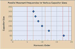
How can you avoid harmonic resonance? One way to solve the problem is applying de-tuned harmonic filters or an appropriately sized capacitor to avoid harmonic resonance. Harmonic filters provide the same 60-Hz reactive compensation as capacitors, but they're typically designed with a parallel resonance point below any expected harmonics on the system. Make sure you consider the existence of harmonic sources on the power system and do a frequency scan and harmonic resonance evaluation to avoid resonance to guarantee the financial benefits of applying capacitive compensation.Special considerations are also very important for switched power factor correction banks. You must evaluate every step (capacitor size) to determine possible resonant conditions. The Figure at left shows a six-step capacitor bank versus harmonic resonant order. The red lines represent the orders to avoid, including the 5th, 7th, and 11th. If this same bank were designed as a harmonic filter, the parallel resonant point at any given stage would be equal to approximately the 3.5th harmonic — well below the 5th harmonic current, which is the lowest significant harmonic on this power system.
Keep in mind the following tips:
-
Always consider harmonic resonance, even when applying a small capacitor on a large system. High harmonic order resonance, such as the 23rd harmonic, can be especially troublesome because significant heat and interference can be created even at low magnitudes.
-
Don't convert 480V capacitors to 480V filters because continuous overvoltage may damage the capacitors.
-
Make sure you account for actual kVAR when applying higher rated capacitors on a lower rated system. Applying 600V capacitors on a 480V system, for example, yields 64% of rated kVAR.
-
If you keep blowing fuses or tripping a breaker on a capacitor bank, measure the capacitor current and look for high harmonic currents.
Everyone's looking for ways to save money, and eliminating power factor penalty charges is one place to start. However, you must consider several factors before investing in capacitors — you may create conditions that result in misoperation or damage to equipment. The number of nonlinear loads on your system will dictate what route to take.
Carnovale is the power quality solution manager with Eaton/Cutler-Hammer in Pittsburgh.
Sidebar: A Self-Correcting Problem?
Harmonic resonance is said to be a self-correcting problem. Most times capacitor fuses will open, capacitor cans will fail, or the source transformer fails (Photo above). Any of these events will lead to the removal of a component from the system, eliminating the resonance condition. However, they're all undesirable results. In a best-case scenario, the electrical control equipment acts erratically.
Sidebar: Measurement Tips
When you take measurements with a power quality analyzer, one or more of the harmonic currents will be uncharacteristically high. The characteristic harmonics normally decrease as frequency increases — the 5th should be higher than the 7th, the 7th higher than the 11th, and so on. Harmonic resonance can be evident in the voltage measurement, but it may not be as obvious or significant.