How to Prevent Stray Welding Current Damage in Your Electrical System
Understanding welding current and learning how a welding circuit interfaces with a building’s electrical system prevents horror stories from happening and leads to correct diagnosis when an incident takes place. Spending a lifetime working in the electrical field, I learned these lessons first-hand.
Starting my career as an apprentice, qualifying as a construction and maintenance electrician, I also added a mining electrical superintendent certificate, a second electrician qualification, and a few investigator certificates along the way prior to my official retirement. For 12 years, I worked as an incident investigator, primarily doing electrical accident investigations that involved electric welding incidents, stray welding current and shock investigations, electrical burns, electrical explosions, fires, and fatality consultations.
The company I worked for was interested in understanding incidents of electric shock. What we found when we became involved with welding incident investigations was that many stick welders (SMAW) suffered hundreds more electric shock incidents than electricians. In fact, if electricians received as many shocks in a year as many welders do in a week, most would seek a new career, provided they were still alive. In the process of understanding electrode shock, we also discovered the phenomena of stray welding current, some that also contributed to welder electric shock.
Stray welding current
Most electrical engineers and electricians never understand the welding circuit past the plug they designed or installed in the shop for the purpose of powering a welding machine. As a member of the national Canadian Electrical Code, I constantly struggle to educate fellow members on this subject.
It is the secondary welding current, the high current, extra-low voltage side that we must be concerned with. If you look at the definition of the welding circuit as defined by the International Electrotechnical Commission (IEC), it says a welding circuit is a “conductive material through which the welding current is intended to flow” (IEV ref 851-14-10 welding circuit). However, if welding current only flowed in the intended circuit, electrical circuits would never be damaged by welding current. A second description, that of the “welding power circuit” (IEV ref 851-14-08 welding power circuit) is “any part of the system which is electrically energized by the welding power of the welding power source.”
Welding leads explained
Let’s first clearly understand the welding lead nomenclature.
• Electrode lead: a secondary circuit conductor transmitting energy from the power source to the electrode holder, gun, or torch. (CAN/CSA W117.2-12) [The one that has the welding electrode holder attached and the welder holds in his/her hand.]
• Workpiece lead: the secondary lead that is attached to the workpiece and completes the welding circuit. Commonly called “ground” or the work lead, it should be attached to the workpiece being welded. (CAN/CSA W117.2-12) [It is definitely not “ground” as the welding power source is designed as an ungrounded system.]
Welding machines may be an AC welding power source, or a DC welding power source with either a positive or negative current at the electrode. Regardless of the power waveform or polarity of current flow, the welding leads retain their names. To be classed as a DC welding power source, the power supply must exhibit less than 10% ripple current.
Creating the damage
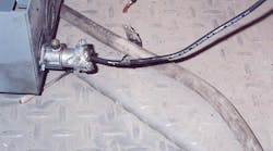
Let’s consider the mobile welding unit called in to do a weld repair at a facility. In a typical commercial or industrial building, the structure is a steel framework; many welders think a good place to attach the workpiece lead would be the nearest steel column near the parking spot for their welding rig — after all, no one wants to drag two cables all the way to the work site. This happens all too often (Photo 1).
The welder fires up his/her welding machine, sets 135A, and drags the electrode lead 100 feet to the work site. He is all set up, strikes an arc, and completes a perfect weld — everyone is happy.
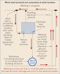
But let’s go back and review the current flow in this specific welding circuit (Figure). Somewhere between 40V and 80V, either AC or DC current, the 135A must flow back to that workpiece lead connected to the building steel 100 lineal feet away — and that 100 feet as the crow flies is possibly four, five, or even 10 times that distance through building steel.
Let’s think about what is available to carry the welding current. There is the building steel, the building grounding system, the many electrical circuit ground conductors, and maybe a few coaxial cables. The truth is that there are many parallel paths to get that 135A back to the power source.
Welding current flowing in anything but the welding cables designed to carry it can cause significant damage in a building’s electrical system. Think what 135A will do to your 14 AWG to 6 AWG building ground conductors, electrical metallic tubing, cable tray, or possibly low-voltage cables.
The truth is many times the damage is not immediately recognized — maybe there was no visible damage during this onetime event as the current load splits through those multiple paths. But that’s not always the case. I remember consulting on one fatality investigation in which the end result of stray welding current and an incomplete electrical inspection before power was restored. The victim died instantly due to a 420mA electrical current flowing across his chest.
The cause
The cause of course is always the same: improper placement of the welding workpiece lead. As electrical professionals, you need to be aware of any welding occurring in your workplace or area of responsibility.
Look at where the welder connects his/her workpiece lead. The workpiece lead should be connected to the work being welded or to the work table if it is a small piece being welded in a shop environment. Wherever the electrode lead is (where the arc occurs), the workpiece lead should be attached in the same location. One contractor enforced this by making the welders tape their leads together as a pair — wherever the electrode lead was taken the workpiece lead went too.
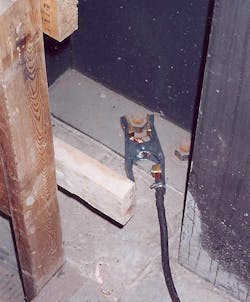
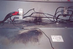
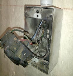
In the case of the fatality from stray welding current mentioned previously, the welder had connected his workpiece lead to a foundation structure bolt more than 100 lineal feet from his weld location. The result was that his welding current flowed through an electrical circuit ground system, destroying conduit fittings (Photos 2 and 3).
The welding circuit
Let’s look at the welding circuit. It is a bit different than what electrical professionals expect to see. The power-consuming electrical arc is exposed and uncontained. In a typical electric circuit, all of the power is expected to be contained in insulated conductors and electrical apparatus. Power is consumed within connected insulated devices. We only expect to see an open arc during a serious fault, and then only when protection devices are set wrong or are installed incorrectly and not properly tested.
Let’s be clear though: A welding circuit has all the characteristics of any other electrical circuit. Whether an AC welding machine or a DC welding machine, the current delivered to the welding electrode must return to the power source and complete the electrical circuit.
The difference is the open arc
This is where the circuits differ. Consider the arc to be the connected electric device. However, as mentioned above, the arc is not contained in an insulated device, and any current flowing through the base metal is free to flow in any available path back to the power source. It must return to the power source through whatever path is available. Keep that path short, and there is less chance of the electrical current straying from the intended path.
In a welding circuit, the arc is the whole purpose of the circuit in that part of the circuit power is not contained. Couple that with an incorrectly placed workpiece lead, and you set the stage perfectly for high current extra-low voltage power to flow indiscriminately through copper ground circuits not designed to carry the hundreds of amps of welding current.
Welding cables, as manufactured, are designed and built with insulation — usually 600V insulation. As they are subjected to extra rough usage, they may not always be maintained as competent insulated conductors, allowing an opportunity for high current extra low voltage power to escape. That damaged cable with bare copper in contact with the steel building structure provides an alternate path for welding current to flow back to the source. If it leaks from the electrode lead, it can just continue to circulate as long as the welding power source is energized. This sets the stage for stray welding current to destroy a building’s electrical systems. So check the quality of your welder’s cables.
Stray welding current incidents
Consider what happens when those parallel paths cross one another, which often happens in cable trays, motor control centers, and other electrical apparatus. Multiple paths with varying resistance with varying currents equal different voltages. I was once called for consultation because a major North American manufacturer had so much welding current flowing throughout the building that the workers’ steel safety work cables connected to the designed steel safety rails arced when they contacted a second piece of metal. Along each parallel path flows not only different amounts of current, but also different voltage levels — hence, the arcing. This plant, which featured several hundred welding machines, had some designers who did not understand that the welding circuit was indeed an electric circuit. In this setting, 11-gauge sheet steel metal strips had been substituted for 4/0 copper welding cable, and many other electric circuit sins had been designed into the workplace. The welders were still able to weld — the current just did not stay in the intended path. The arcing seen on elevated work areas were just one of the dramatic outcomes. Work stoppage was the immediate result — fortunately no one died.
The cause
When ground conductors show signs of overheating, always consider welding current to be the cause: 1st, 3rd, 5th, 7th, and 9th harmonics wreak havoc with neutral conductors, but not grounds.
Examination of workplace power cords in the vicinity of the welding workplace will often reveal burned U ground plug pins, but the straight blades are in good shape. The culprit is stray welding current caused when some grounded power tool was in the vicinity of welding, and the welding current flowed through the power tool/ground conductor back to the building electrical system, which is at the same potential as the welding workpiece lead.
How the failure occurs
In the incident where the young victim died, the welding current had melted the cast metal connectors of the electrical metallic tubing (EMT) for the temporary construction power supply. In this case, it was the circuit supplying the welding machine. Heating of the metal fittings caused the phase conductor insulation to melt, connecting the remaining ground circuit with the phase conductor.
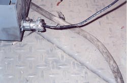
In a more recent event in a welder training facility, stray welding current overheated the ground conductor, which melted through a phase conductor inside a welder power receptacle and caused an electrical explosion (Photo 4) and the protective device to operate. Chasing ghosts and goblins, the electrician did not understand the fault and set out to look for a faulty protective circuit breaker or other mysterious cause. Luckily, the welding instructor was familiar with this type of incident and set the electrician on the right path. Then he asked me to review his plan and make necessary recommendations.
I’ve seen one case where welding current flowed through a low-voltage cable ground conductor, destroying several hundred feet of cable from a remote 600V receptacle all the way to the motor control center. This was the system that had fed the welding machine, which is often the case.
Conclusion
The moral of this story is train yourself to recognize the destructive forces of welding current. Doing so will go a long way toward preventing stray welding current damage in your facility. If it should occur, understand the how and why — and search out the path so that damaged systems can be replaced in the most timely and economical methods available. This will ensure your electrical systems remain safe. Only correct positioning of both welding leads at the site of the welding process will control stray welding current. Otherwise, with the welding arc, high current extra low-voltage electric power is free to roam indiscriminately throughout your building.
Hisey is retired and lives in Edmonton, Canada. Currently, he serves as Chair of the T/C for CSA W117.2; chair of CSA C232 (CSC26) Electric Welding Equipment and a member of national Canadian Electrical Code CSA C22.1. He also represents Canada on Commission VIII Welding Health and Safety with the International Institute of Welding. He can be reached by email at [email protected].
