When a crew employed by a local electric utility set out to conduct a DC hi-pot test on a new circuit breaker, the task seemed like nothing more than a routine call. Unfortunately, the events that unfolded that day proved to be anything but typical for one unsuspecting technician.
The purpose of a DC hi-pot test is to determine if there is any leakage taking place in and around the insulator bushings. General procedures for this test are quite standard. Hi-pot test leads are attached to the top and bottom of the breaker bushings. The crew performing the test first isolates the breaker from the circuit and closes the breaker. Next, they short out the low side terminal bushings of each of the three phases to ground. This part of setup doesn’t change throughout the test. Then, one-by-one, the crew applies a high-voltage direct current (450kV DC) to the high side contact of each phase. Once the high voltage has been applied, the crew checks for any leakage current around the contacts. In this particular case, no voltage was applied to the midpoint location between the two stacked capacitor units.
The Scene
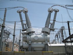
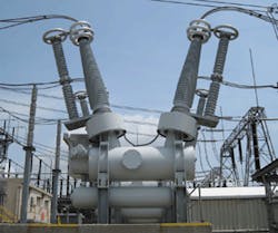
The breaker being tested was a single pressure SF6 circuit breaker. Note: Sulfur hexafluoride (SF6) is an extremely good insulator — roughly 2.5 times better than air. The breaker was equipped with transient recovery voltage (TRV) suppression capacitors. TRV capacitors also go by the name “snubber” capacitors, located on each of the three individual phases. In this particular case, each snubber capacitor was comprised of two individual capacitors connected in series with each other to act as a single larger sized unit. During the course of the test, the site remained dry and clean.
The Accident
The 450kV DC test voltage was first applied to Phase A on the “high” side of the bushing for 5 min. After Phase A successfully passed the test, the test voltage was removed from the high-side bushing and allowed to sit for 5 min. This rest period allowed the voltage to dissipate before re-grounding the high-side bushing. Using an insulated grounding stick, the technician then reapplied the ground to the high side of the snubber capacitor. The crew waited another 20 min. to allow the high side of the breaker for Phase A to fully discharge. However, no protocol addressed the center point of the two stacked capacitors.
In preparation for the same test on Phase B, one member of the crew (a lineman) was in a grounded lift bucket about 15 ft above ground. Handling the mechanical duties of making the connections ordered by the company’s engineer supervising the test, the lineman proceeded to remove the grounding cable from the high-side terminal of Phase A. According to eyewitnesses, it was at this point that a fairly large ball of light emitted from the midpoint location and struck the lineman. Only protected by leather gloves at this point in time, the lineman suffered burns and muscle/organ damage as a result of the accident.
Although the incident didn’t kill him, he experienced body tremors (e.g., the “shakes”) for several years after the accident as well as suffered from post traumatic stress disorder. Fortunately, he did not fall out of the bucket, but he did black out briefly yet remained at least partially conscious through the entire event. After lowering the bucket to the ground, the victim’s fellow crew members administered first aid until paramedics arrived minutes later.
It is important to note that this was the second such accident to occur when testing this particular type of circuit breaker. One year earlier, another lineman who worked for the same electric utility was injured in similar fashion during a hi-pot test conducted at a substation located approximately 100 miles away. The arrangement of the capacitors was the same in both accidents. Although testimony was not as clear in the first case, all witnesses agreed that after the high side of the capacitor pair was grounded (with the assumption that nothing was needed to be done with the midpoint), something happened to the lineman — hospital tests later confirmed it was most likely an electric shock. After collecting workers’ compensation and later retiring, this lineman did not require extensive follow-up therapy like the victim in the second accident.
The Lawsuit
We were hired by the capacitor and circuit breaker manufacturer to investigate the accident and generate a report of our findings. Both victims (linemen from first and second accident) initiated a joint lawsuit against the power company and the manufacturers of the capacitors/breakers.
Investigation and Analysis
It’s important to understand the electrical design parameters of the snubber capacitor arrangement in this particular case before diving into analysis details. This type of design creates the following three states:
- OFF or zero voltage state, when both the high side and low side of the snubber capacitor are grounded.
- ON state, when 450kV is applied to the high side of the snubber.
- The intermediate or transitional state between these two prior states. It is this intermediate state that is most dangerous to work on or near.
If a voltage spike occurs during the intermediate state, then electricity can jump across the ceramic insulators of the snubber capacitor and travel up to 30 ft in air. This arc can easily shock or electrocute someone, as was the case in this particular situation.
Upon closer examination, we made an interesting discovery. The circuit breaker was originally designed with a single body 2nF capacitor per phase, intended to handle voltage stress levels of up to 500kV DC without breakdown of the insulator. However, a new design engineer working for our client (manufacturer of the capacitors/breakers) later revised the circuit to employ two 4 nF capacitors stacked in series rather than a single unit. Carried out to save money, this approach was approved by the company design team for the “next generation” of breakers that it sold. Although this new design arrangement produced the same overall rating as the original single capacitor design, each stacked capacitor unit could now only be stressed to 250kV.
As a rule of thumb, the money spent on building a capacitor to operate safely at a specific voltage level will increase by at least a factor of four each time you double the maximum voltage stress rating of the capacitor. The reason for this is the cost must cover the construction needed to handle the higher power, and electric power varies as voltage-squared. Consequently, a design engineer can realize a big up-front equipment cost savings by decreasing the voltage stress level of a specific component.
In an ideal setting, two capacitors placed in series split the voltage applied across them evenly. Capacitors can be thought of as infinite ohm resistors, but the resistance of this arrangement can be many trillions of ohms. The problem with this type of design is the capacitor manufacturer cannot maintain strict control of the capacitor geometry. If the geometry between two units is off by a mere 1%, then this will create a major problem. In this case, a 1% deviation at 450kV is 4,500V. This is the voltage at the midpoint of the capacitors at the conclusion of the hi-pot testing, after the high side is grounded.
Our investigation revealed negligence on the part of the electric utility. The manual that came with the circuit breaker, as supplied by the manufacturer, specified that discharge of the capacitor(s) was to be done by placing all terminals (high, low, and middle) to ground. The work crew only had the high and low terminals grounded at the time of the accident. Furthermore, basic engineering principles show that when two capacitors are placed in series, full grounding does not take place unless all three terminals are grounded. Nevertheless, the crew (including both linemen and the engineers) overlooked the additional grounding of the midpoint of the capacitors. The linemen did not know it was required. The engineers never clearly stated what they believed before the accident; however, their instructions to the crew led them to believe that only the top and bottom of the two capacitors in series were sufficient to be grounded in order to make the arrangement safe.
A contributing factor in this accident was the prior work history on these types of breakers equipped with single body 2nF snubber capacitors. The electric utility felt that additional training should have been mandated by the capacitor and circuit breaker manufacturers beyond simply changing a specification in the service manual. Given the fact that there was an almost identical accident one year earlier, the electric utility felt the capacitor/breaker manufacturer should have taken a more proactive approach in explaining the changes needed in hi-pot testing of its revised product.
The Verdict
The case was settled out of court for an undisclosed amount prior to going to trial. Our firm’s forensic findings helped significantly reduce our client’s settlement costs, forcing the electric utility to accept a greater share of the responsibility and settlement payment. Originally looking at a realistic payout of several million dollars per victim, our client ended up with a payout under $500,000. This reduction in judgment was due to the fact that our client had specific instructions on both breaker systems stating that during the powering down of a hi-pot test the midpoint of the capacitors must be grounded. The electric utility supervisors (engineers supervising the tests) overlooked this point. However, our client was still held partially liable for two reasons:
- Prior to using two capacitors in series, our client used a single capacitor with no midpoint to worry about. When the company changed the design, it should not only have changed the directions that came with the breakers (which it did), but also have taken a more proactive approach to talk to the engineers at the electric utility to which it sold products about what that change would mean during testing.
- Safety protocols that were spelled out by the capacitor/breaker manufacturer were violated in the first accident. After an investigation, the electric utility put the matter to rest. Although the substance of its investigation was not made known, it should have given the breaker/capacitor manufacturer reason to question the safety protocols during the hi-pot testing. Failure of our client to act after the first accident can also be considered as partial blame.
Lessons Learned
In theory, the voltage at the midpoint between two equally sized capacitors placed in series is zero when the high and low points are grounded. However, geometry and other inconsistencies in design can make the capacitors unbalanced. A mere 1% mismatch (or larger) in the capacitor’s internal resistances can allow dangerous voltage levels to form. It is the capacitor’s charge storage ability that maintains this voltage imbalance when the high side of the capacitor is grounded. In this accident, the crew thought that by grounding the high and low sides of the capacitor they would be safe, but the 4,500V potential difference inflicted extensive burns over the lineman’s body and caused muscle pain/spasms for years to come. For hi-pot testing or any high-voltage applications, never place two capacitors in series unless you are prepared to ground the midpoint and both ends of each unit prior to performing any testing/maintenance work. Also make sure your instructions are clear to persons in the field doing the actual testing.
Hmurcik is a consultant at Lawrence V. Hmurcik, LLC. He can be reached at: [email protected]. Patel is a PhD candidate at the University of Bridgeport, Bridgeport, Conn. He can be reached at: [email protected].

