Calculating Touch Voltages and Electric Shock Risk in Low-Voltage Systems
The analysis of magnitudes and durations of touch voltages in cable installations can provide electrical professionals with a better understanding of the requirements of Art. 250 of the NEC regarding the protection against electric shock. Such analysis disproves a common misconception held among many electrical professionals that providing an installation with a proper ground electrode is a sufficient condition to eliminate electric shocks in the event of a fault. In reality, even in correctly designed and erected installations, the risk of electric shock does exist, and its magnitude can be quantified through the study of touch voltages.
The effects of electric currents passing through the human body primarily depend upon their intensities and the duration of the contact, as well as upon the specific pathway through the person. The accidental flow of body currents is caused by the exposure to touch voltage. Although this term does not appear in the NEC, we can define it as the potential difference appearing between simultaneously accessible non-current-carrying metal enclosures (live due to the failure of the basic insulation) and any other grounded part (e.g., the floor, soil, water pipes in buildings, etc.).
Touch voltages are harmful only if their duration exceeds a safe permissible time, as indicated in IEC standards, but also in IEEE Std 80-2000, “Guide for Safety in AC Substation Grounding.” Thus, the protection against electric shock through disconnection of the supply is only valid if, and only if, the clearing time of protective devices does not exceed the safe permissible time. In addition, the safety measure of disconnection of supply can only be effective if protective devices are in partnership with equipment grounding conductors.
Section 250.134 of the 2014 NEC prescribes that “non-current-carrying metal parts of equipment, raceways, and other enclosures, if grounded, shall be connected to an equipment grounding conductor by one of the methods specified in 250.134(A) or (B).” Equipment grounding conductors (EGCs), connected to a common terminal (namely the main ground bus of the installation) must provide low-impedance fault-current paths to allow the prompt operation of overcurrent protective devices. Tripping protective devices within the aforementioned conventional safe time, as established by codes and technical standards as a function of the magnitude of the touch voltage, guarantees that the contact is not harmful to persons.
The above requirements of the EGCs are essential when the protection against electric shock is ensured through the automatic disconnection of the supply, which is the most common protective measure employed in low-voltage installations. Alternative protective measures are possible although uncommon.
Prospective touch voltages
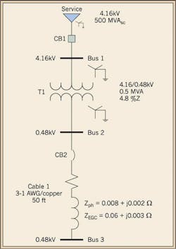
In NEC-based installations, prospective touch voltages coincide with the voltage drops across the EGC connecting the faulty equipment to the main ground bus. To better clarify, consider the simplified single-line diagram of Fig. 1, where Bus 3 is ground faulted. Let us build the fault-loop equivalent circuit and calculate the voltage drop on the EGC connected to Bus 3, as well as the fault current flowing subsequent to the ground fault.
The electric utility short circuit contribution Ssc at the service entrance is 500MVAsc at the voltage V1= 4.16kV, with an XS/RS ratio of 10; the impedance (Zs) of the source can be calculated as follows:
Equation 1:
Equation 2:
Equation 3:
XS = 0.034 Ω
The transformer (T1) has a percent impedance (Z%= 4.8% on a 0.5MVA base), with an XT1/RT1 = 4.7, an apparent power rating ST1 = 0.5MVA, and a secondary voltage V2 = 0.48kV. Hence,
Equation 4:
Equation 5:
Equation 6:
Equation 7:
Cable 1 is 1 AWG and 50 ft long; the EGC, of same length, is 10 AWG. Both wires are in steel conduit.
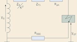
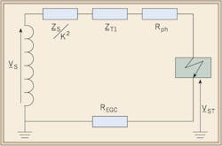
The prospective touch voltage VST at Bus 3 can be calculated based on the fault-loop equivalent circuit shown in Fig. 2.
When circuit conductors have a wire size less than 2 AWG, their reactance may reasonably be neglected in calculations, being at most 18% of their resistance; thus, conductor resistances may be used instead of impedances. Thus:
Equation 8:
The underlined quantities represent complex numbers, where: Vs is the phase-to-ground voltage at the source; Zs is the internal impedance of the source; k= V1/V2 = 4,160V/480V = 8.666 is the winding turn-ratio of the transformer T1; REGC is the resistance of the equipment grounding conductor; Rph is the resistance of the cable phase conductor; ZLoop is the total fault-loop impedance, comprising the source referred to the secondary side of the transformer, the resistances of the transformer, cable phase conductor and equipment grounding conductor up to the point of fault.
If we plug into equation 8 the above numerical values in correspondence with their respective quantities, we will obtain:
Equation 9:
By applying Ohm’s law, we can also determine the fault-loop current:
Equation 10:
Thus, the touch voltage and the fault-loop current will respectively have the magnitudes of 224V and 3,471A.
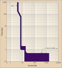
In correspondence with this amount of fault-loop current, the protective device CB2, in charge of the protection of Cable 1 and Bus 3, will trip in approximately 0.05 seconds (Fig. 3). The clearing time of 0.05 seconds represents, therefore, the maximum duration of the contact with the energized part.
Permissible body current
The contact with energized parts will cause the circulation of body currents, whose intensities and durations should be less than the values that can cause ventricular fibrillation of the cardiac muscle.
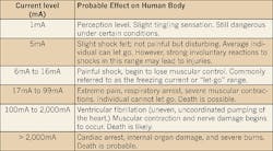
OSHA offers an interpretation of the effects of 60-cycle currents passing through the human body, based on fault duration of 1 second, as a consequence of a hand-to-foot contact (see Table). Note: The Table can only be applied for fault duration of 1 second.
An analytical approach to determine the maximum tolerable current for any given fault duration has been provided by Charles F. Dalziel — a major contributor to the field of electrical safety — in 1946, and referenced in IEEE Std 80-2000, “Guide for Safety in AC Substation Grounding.” Dalziel ascertained that 99.5% of the population can withstand for a time ts (s) the passage of a current of magnitude IB (A) without incurring ventricular fibrillation; this allowable body current can be determined with equation (11), assumed that the population body mass is 50 kg (110 lb).
Equation 11:
The body current of Equation (11) is based on tests with fault durations ranging between 0.03 seconds and 3 seconds. This equation cannot be used for very short or long fault durations. To further clarify, IB is the current which has the 0.5% probability of triggering the ventricular fibrillation; therefore, it can also be referred to as the non-fibrillating body current.
Resistance of persons to ground
The total resistance of a person to ground is the series of the human body resistance RB from hand-to-feet and his/her resistance-to-ground RBG. In low-voltage systems, it is assumed that contact resistances of hand and foot are zero (i.e. the person may have wet skin), and gloves and shoes are not worn; therefore, conservatively no additional resistances need to be considered.
The human body resistance is assumed to be 1 kΩ in IEEE 80; however, IEC TS 604479-1, “Effects of Current on Human Beings and Livestock,” details statistical values of body resistance as function of the touch voltage: at 125V, 95% of the population offers a body resistance of 1.337 kΩ.
In the absence of a floor, RBG is the resistance of the person’s feet, which are generally represented as two conducting disks of radius r = 0.08 m, in parallel on the soil. The two disks in parallel have a ground-resistance in ohms given approximately by equation (12).
Equation 12:
where r is the superficial resistivity in W·m of a homogenous soil.
If the person stands on floors, RBG is the resistance-to-ground of the floors themselves; as an example, the minimum resistance in wet hardwood floors can be assumed as 670 Ω.
Permissible prospective touch voltage
Base on Equation (11), the expression of the maximum permissible touch voltage, which can be withstood without suffering ventricular fibrillation by 95% of the population, is given in volts by equation (13), as a function of the touch duration.
Equation 13:
By considering the person in a building with hardwood floors and a fault clearance time of the protective device (ts = 0.05 s), as shown in Fig. 3, we will obtain the maximum permissible touch voltage:
Equation 14:
By comparing the value obtained with Equation 14 with the actual touch voltage VST = 224V calculated at Bus 3 with Equation 9, we immediately see that the VST < VSTP, thus persons are to be considered protected against electric shock, even though the magnitude of the prospective touch voltage VST exceeds 50V.
If the same protective device cleared the fault in 1 second in correspondence with the same ground-fault current, the VSTP would be 194V as shown in Equation (15).
Equation 15:
By comparing this value with the actual touch voltage VST calculated at Bus 3 with Equation 9, we immediately see that the VST > VSTP, thus persons are not to be considered protected against electric shock.
Drawing conclusion
Engineers generally perform power flow calculations to determine, among other things, voltage drops at each node of the network. Voltage drop criteria will determine the minimum size of cables. To properly size the cable and improve safety, engineers should also perform touch voltage calculations and compare the results against the permissible values obtained with equation (13). As a consequence, criteria to determine the minimum size of cables should also include the minimization of prospective touch voltages.
The fault-loop impedance and the equipment grounding conductor impedance, ultimately responsible for the magnitude of touch voltages, can be inadvertently increased due to the use of extension cords, which, in many cases, become permanent components of the installations. Professional engineers should also take their length and wire size into account, based upon the layout and actual number of outlets available in rooms.
Mitolo is a an advisory engineer for Eaton Corp. and Liu is senior principal electrical engineer for ETAP. They can be reached at [email protected] and [email protected].
