Over the past few years, you may have noticed more arc flash labels appearing on electrical equipment. Arc flash labeling requirements were first introduced in the National Electrical Code (NFPA 70) in 2002 and subsequently appeared in NFPA 70E in 2009. While both standards require arc flash labels, there are some differences in requirements. This article will focus on the new labeling requirements resulting from recent revisions to these standards. It will also discuss some “sticky” situations relative to labeling as well as best practices and considerations for arc flash labels.
Arc flash labeling is just one piece of a multiple-step process. Labeling alone does not safeguard people from the hazards associated with electricity; rather, it complements the other important steps of a comprehensive electrical safety policy. The components of a good policy include:
• Regularly audit your electrical safe work practices (ESWP) policy.
• Conduct an electrical system study to determine the existing arc flash hazards, and label the equipment accordingly.
• Ensure adequate supplies of appropriate personal protective equipment (PPE) and tools.
• Conduct regular safety training and employee assessments.
• Maintain all electrical distribution system components.
Labeling requirements: NEC
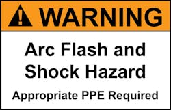
The NEC contains electrical installation requirements. The arc flash labels required by the NEC do not contain circuit specific information, meaning they can be either field or factory applied. These labels are intended to warn about the existence of an arc flash hazard (see Fig. 1). Since being introduced in 2002, there have been changes with those requirements in every revision cycle.
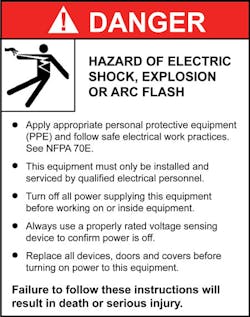
NEC labels are formatted to comply with the ANSI Z535 standards and use colors, signal words, and messaging to alert people to hazards (Fig. 2). NEC labeling requirements are found in Sec. 110.16 and are also referenced in Sec. 110.21(B). The underlined text below reflects additions made to the 2014 NEC.
• “110.16 Arc-Flash Hazard Warning. Electrical equipment, such as switchboards, switchgear, panelboards, industrial control panels, meter socket enclosures, and motor control centers, that are in other than dwelling units, and are likely to require examination, adjustment, servicing, or maintenance while energized, shall be field or factory marked to warn qualified persons of potential electric arc flash hazards. The marking shall meet the requirements in 110.21(B) and shall be located so as to be clearly visible to qualified persons before examination, adjustment, servicing, or maintenance of the equipment.*
• 110.21(B) Field-Applied Hazard Markings. Where caution, warning, or danger signs or labels are required by this Code, the labels shall meet the following requirements:
1) The marking shall adequately warn of the hazard using effective words and/or colors and/or symbols.*
2) The label shall be permanently affixed to the equipment or wiring method and shall not be hand written.
Exception to (2): Portions of labels or markings that are variable, or that could be subject to changes, shall be permitted to be hand written and shall be legible.
3) The label shall be of sufficient durability to withstand the environment involved.*”
* Informational notes have been omitted here for space considerations.
Labeling requirements: NFPA 70E
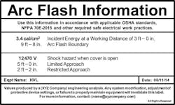
NFPA 70E is a work practices standard. The arc flash labeling requirements in NFPA 70E first appeared in the 2009 edition, and, like the NEC, these requirements have expanded with each subsequent edition. NFPA 70E labels are informative and contain equipment and site-specific information. They relate to work practices and are required to contain field marked information which, at minimum, includes voltage, arc flash boundary, and arc flash information, such as the incident energy and corresponding working distance (Fig. 3).
Labeling requirements in the 2015 edition of the standard are found in Sec. 130.5(D); they were referenced in Sec. 130.5(C) in the 2012 Edition. The underlined text below reflects the additions made to the new 2015 edition.
• 130.5(D) Equipment Labeling. Electrical equipment such as switchboards, panelboards, industrial control panels, meter socket enclosures, and motor control centers that are in other than dwelling units and that are likely to require examination, adjustment, servicing, or maintenance while energized shall be field-marked with a label containing all the following information:
(1) Nominal system voltage
(2) Arc flash boundary
(3) At least one of the following:
a. Available incident energy and the corresponding working distance, or the arc flash PPE category in Table 130.7(C)(15)(A)(b) or 130.7(C)(15)(B) for the equipment, but not both
b. Minimum arc rating of clothing
c. Site-specific level of PPE
Exception: Labels applied prior to Sept. 30, 2011, are acceptable if they contain the available incident energy or required level of PPE.
The method of calculating and the data to support the information for the label shall be documented. Where the review of the arc flash hazard risk assessment identifies a change that renders the label inaccurate, the label shall be updated. The owner of the electrical equipment shall be responsible for the documentation, installation, and maintenance of the field-marked label.
Sticky situations
NFPA 70E provides minimum requirements for labeling. These are fine for a simple, radial power system (i.e., one configuration, one value, one label). However, not all systems are this simple. There are cases where electrical equipment may have two or more possible incident energy values (or PPE requirements) because of different operating scenarios. Examples include:
• Multiple sources/configurations
• Maintenance switches or other temporary protection
• Arc-resistant switchgear
• Equipment construction
Multiple sources/configurations — This situation is becoming increasingly common and can have several variations. Examples include: Utility + Standby Generation; Main + Alternate Utility Sources; and Co-Generation/ Microgrid. Large facilities and/or complex systems may have multiple variations and scenarios (e.g., a large data center with parallel generating units, utility sources, tie breakers, paralleled UPS modules, closed-transition transfers, etc.). The available fault current in each scenario can vary significantly, depending on which source(s) is connected. This impacts the fault clearing time which, in turn, affects incident energy levels.
Maintenance switches or other temporary protection — This potentially sticky situation features a two-position switch, allowing a worker to switch between “normal” and “maintenance” modes. The normal mode allows delayed tripping but full coordination. The maintenance mode allows faster tripping, which lowers arc flash incident energy, but may sacrifice some coordination in the system. Because of the variation in tripping times between the two modes, there will generally be two possible incident energy levels downstream of a maintenance switch. Labeling with “normal mode” values is the conservative approach, but if that method is chosen, users need to consider how to communicate the “maintenance mode” value to the worker.
Arc-resistant switchgear — According to IEEE C37.20.7-2007, IEEE Guide for Testing Metal-Enclosed Switchgear Rated Up to 38kV for Internal Arcing Faults, use of such equipment “…is intended to provide an additional degree of protection to the personnel performing normal operating duties…under normal conditions.” Normal operating duties include opening or closing switching devices, connecting or disconnecting withdrawable parts, and/or taking readings from externally mounted monitoring equipment.
During normal operations and normal operating conditions, there is no analytical method to calculate the incident energy level within the protected perimeter of the gear, and meeting the requirements of the IEEE standard does not necessarily correspond to any particular incident energy level. What about work tasks or situations not included in “normal conditions” or “normal operating duties”? In such cases, the full calculated incident energy level would apply. As a result, there are at least two potential exposure levels, depending on the state of the equipment and the task being performed.
Equipment construction — There can be different zones of protection within a single piece of equipment. For a switchboard or switchgear with a main breaker, the incident energy at the line side of the main is likely different (higher) than the incident energy at the load side of the main. When equipment construction is considered, is there any practical difference between these two protection zones? Can arcing faults propagate to the line side of the main? Cases such as this require some degree of engineering judgment. For example, when is it valid to consider multiple protection zones in one piece of equipment? If they exist, how should the equipment be labeled?
As noted in Clause B.12 of IEEE Standard 1584-2002, Guide for Arc Flash Hazard Calculations, “If an arcing fault can be initiated on the line side of a main protective device in an enclosure, that protective device should not be utilized for the calculations, instead, the upstream protective device should be used. That is because only an upstream protective device can be considered to provide protection for an arcing fault on the line side of the main protective device in a downstream enclosure.”
How to label equipment with sticky situations. As part of the risk assessment, users should consider the effect of the system operating scenarios on the arc flash hazard analysis and labels. This applies to PPE selection done both by incident energy calculations and by application of the PPE selection tables in NFPA 70E.
But what about the actual labels? If multiple incident energy levels are possible at a piece of equipment — and there is only a small spread in the potential incident energy levels between them — the decision may be to go with the worst-case label. If there is a larger spread in values, application of multiple labels can be considered, though the conservative approach would be to again go with the worst-case scenario. If only a single label is used on arc-resistant equipment, the label should denote the “open door” value, not the reduced value based on arc-resistant protection. An alternative approach would be to affix more than one label on the equipment, or have a label show more than one value. However, if equipment is labeled with more than one PPE category or incident energy value, the potential for confusion is introduced. Following are recommended guidelines for these situations:
1. Make sure the labels are clear as to when different levels apply.
2. Make sure employees demonstrate an ability to properly determine which levels are applicable based on the state of the system.
3. Make sure training and procedures address these circumstances.
4. Don’t go overboard. Equipment with 10 different arc flash labels would confuse the most competent of workers. Keep things as simple as possible.
In all cases:
• The label (or study) should identify the scenario the analysis is based upon.
• Workers must be trained to identify the state of the system and determine the applicable protection requirements.
• If necessary, add steps to the electrical safe work practices policy to ensure this is considered as part of the job hazard analysis.
Best practices and considerations. Equipment labels should comply with standards, contain clear and concise information, and be legible. Materials used for the label (including the adhesive) should be durable and able to withstand the operating environment.
As stated earlier, the minimal requirements for NFPA 70E arc flash labels are: voltage, arc flash boundary, and incident energy and working distance (or PPE category). However, as a best practice, you may want to consider adding additional information, such as the date, references to standards, an engineering contact, and boundary information.
NFPA 70E labels should be placed where they are readily visible (eye-level, if practical) with at least one label per vertical section of equipment. DO NOT cover up any existing NEC warning labels that may be in place; however, do remove old NFPA 70E arc flash information labels when applying new ones. In some cases, labels that combine both safety messages and arc flash information may be acceptable, but watch out for mixed messages or conflicting signal words or colors on the same piece of equipment.
The ultimate goal of arc flash labeling is to allow a qualified employee to correctly understand, interpret, and apply the information on the labels. The labeling approach, employee training program, and electrical safe work practices policy/documentation must be all aligned.
Parsons is a senior staff engineer for Schneider Electric Engineering Services in Austin, Texas. He can be reached at [email protected]. West is a senior staff engineer for Schneider Electric USA, formerly known as Square D Co. in Oxford, Ohio. He can be reached at [email protected].
