Stumped by the Code? NEC Requirements for Sizing Boxes for Conductor Fill
All questions and answers are based on the 2014 NEC.
Q. What are the NEC requirements for sizing boxes for conductor fill?
A. Boxes containing 6 AWG and smaller conductors must be sized in an approved manner to provide free space for all conductors, devices, and fittings. In no case can the volume of the box, as calculated in Sec. 314.16(A), be less than the volume requirement as calculated in Sec. 314.16(B) [314.16]. Conduit bodies must be sized in accordance with Sec. 314.16(C).
Note: The requirements for sizing boxes and conduit bodies containing conductors 4 AWG and larger are contained in Sec. 314.28. The requirements for sizing handhole enclosures are contained in Sec. 314.30(A).
Box volume calculations — the volume of a box includes the total volume of its assembled parts, including plaster rings, extension rings, and domed covers that are either marked with their volume in cubic inches or are made from boxes listed in Table 314.16(A).
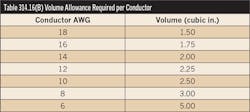
Box fill calculations — The calculated conductor volume determined by Sec. 314.16(B)(1) through (5) and Table 314.16(B) are added together to determine the total volume of the conductors (see Table below), devices, and fittings. Raceway and cable fittings, including locknuts and bushings, aren’t counted for box fill calculations.
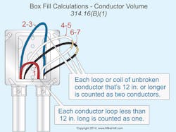
Conductor volume — Each unbroken conductor that runs through a box (and each conductor that terminates in a box) is counted as a single conductor volume in accordance with Table 314.16(B). Each loop or coil of unbroken conductor having a length of at least twice the minimum length required for free conductors in Sec. 300.14 must be counted as two conductor volumes. Conductors that originate and terminate within the box, such as pigtails, aren’t counted at all (Figure).
Note: According to Sec. 300.14, at least 6 in. of free conductor, measured from the point in the box where the conductors enter the enclosure, must be left at each outlet, junction, and switch point for splices or terminations of luminaires or devices.
An Exception in this Section notes that equipment grounding conductors, and up to four 16 AWG and smaller fixture wires, can be omitted from box fill calculations if they enter the box from a domed luminaire or similar canopy, such as a ceiling paddle fan canopy.
Cable clamp volume — One or more internal cable clamps count as a single conductor volume in accordance with Table 314.16(B), based on the largest conductor that enters the box. Cable connectors that have their clamping mechanism outside of the box aren’t counted.
Support fitting volume — Each luminaire stud or luminaire hickey counts as a single conductor volume in accordance with Table 314.16(B), based on the largest conductor that enters the box. Note: Luminaire stems don’t need to be counted as a conductor volume.
Device yoke volume — Each single-gang device yoke (regardless of the ampere rating of the device) counts as two conductor volumes, based on the largest conductor that terminates on the device in accordance with Table 314.16(B). Each multi-gang device yoke counts as two conductor volumes for each gang, based on the largest conductor that terminates on the device in accordance with Table 314.16(B).
Equipment grounding conductor volume — All equipment grounding conductors in a box count as a single conductor volume in accordance with Table 314.16(B), based on the largest equipment grounding conductor that enters the box. Insulated equipment grounding conductors for receptacles having insulated grounding terminals (isolated ground receptacles) [250.146(D)] count as a single conductor volume in accordance with Table 314.16(B). Note: Conductor insulation isn’t a factor that’s considered when determining box volume calculations.
This example problem helps explain these concepts in a practical application:
How many 14 AWG conductors can be pulled through a 4-in.-square × 2½-in.-deep box with a plaster ring with a marking of 3.60 cu. in.? The box contains two receptacles, five 12 AWG conductors, and two 12 AWG equipment grounding conductors.
Step 1: First, determine the volume of the box assembly [314.16(A)] as follows:
Box 30.30 cu. in. + 3.60 cu. in. plaster ring = 33.90 cu. in.
A 4 × 4 × 21/8 in. box has an interior volume is 30.30 cu. in., as listed in Table 314.16(A). Note: The gross volume of a box based on Table 314.16(A) dimension (4 in. × 4 in. × 21/8 in. = 34 cu. in.) doesn’t take into account the actual volume of the material used to make the box. This is why the interior volumes on this table are smaller than the overall volumes.
Step 2: Next, determine the volume of the devices and conductors in the box:
Two – receptacles = 4 – 12 AWG conductors
Five – 12 AWG conductors = 5 – 12 AWG conductors
Two – 12 AWG ground conductors = 1 – 12 AWG conductor
This equates to a total of ten 12 AWG conductors: 10 × 2.25 cu in. = 22.50 cu in.
Step 3: Determine the remaining volume permitted for the 14 AWG conductors:
33.90 cu in. – 22.50 cu in. = 11.40 cu in.
Step 4: Determine the number of 14 AWG conductors permitted in the remaining volume:
14 AWG = 2.00 cu in. each [Table 314.16(B)]
11.40 cu in. ÷ 2.00 cu in. = 5 conductors


