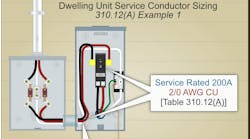
PV systems, energy storage systems, or generators operating in parallel with the electric utility are examples of interconnected power sources. Equipment operating in parallel with power production sources must be listed for the required interactive function [Sec. 705.6], as shown in Fig. 1.
Where power production sources operate in parallel with the electric utility, a permanent plaque, label, or directory must be installed at each service disconnect location or an approved readily visible location [Sec. 705.10]. This identification method must meet specific requirements. For example, it must indicate the emergency telephone numbers of any off-site entities servicing the interconnected power production sources.
Service connection
Power production sources can be connected to the electric utility by one of the three methods listed in Sec. 705.11(A)(1) through (3). For example, they can be connected to an additional set of service entrance conductors per Sec. 230.40 Exception No. 5.
The supply-side conductors to interconnected power production equipment must have an ampacity of at least 125% of the continuous current rating and be at least 6 AWG copper or 4 AWG aluminum (or copper-clad aluminum) [Sec. 705.11(B)].
A disconnecting means per Art. 230, Parts VI through VIII must be provided to disconnect the supply conductors to interconnected power production equipment [Sec. 705.11(D)]. Supply-side conductors terminating at the power production disconnect must have overcurrent protection per Art. 230, Part VII. [Sec. 705.11(F)].
Metal enclosures, metal raceways, and cable methods containing supply-side conductors must be bonded per Art. 250, Parts II through V and VIII [Sec. 705.11(E)].
Connection to service conductors for interconnected power production equipment must comply with the following [Sec. 705.11(C)]:
(1) Splices and taps to service conductors must be per Sec. 230.46.
(2) Modifications to equipment to accommodate supply-side connections must be per the manufacturer’s instructions, or the equipment modification(s) must be field evaluated and field labeled.
(3) Supply-side connections within meter socket enclosures under the exclusive control of the electric utility are permitted only where approved by the utility.
Load side connection
The rules for feeders and bus taps [Sec. 705.12] have changed with the 2023 revision. Some highlights:
Power production source output conductors can be connected to the feeder or feeder equipment (load-side of service disconnect) [Sec. 705.12].
Where the power production source connection is made to a feeder [Sec. 705.12(A)], the feeder must have an ampacity of at least 125% of the power production source nameplate current per Sec. 705.28(A). If the connection to a feeder is not at the opposite end of the feeder overcurrent protective device (OCPD), that portion of the feeder on the load side of the power production source connection must have an ampacity not less than:
(a) The feeder OCPD, plus 125% of the power production source current rating.
(b) The feeder OCPD rating placed at the load side of the power production source.
A disconnecting means must be provided to disconnect the power production source equipment output conductors [Sec. 705.20], as shown in Fig. 2.
It must be one of the four types listed in Sec. 705.20(1)(a) through (d). An example would be a load-break-rated pull-out switch, and it must meet the six requirements of Sec. 705.20(2) through (7). For example, it must be externally operable.
Power production source output conductors must comply with Sec. 705.25(A) through (C). For example, flexible cords used to connect moving parts of power production equipment, or used for ready removal for maintenance and repair, must be listed and identified as Type DG cable, suitable for extra-hard usage, and water resistant.
Output current and circuit sizing
The power production source output current is equal to the sum of the output current of the power production equipment nameplate current rating [Sec. 705.28(A)(1)].
The power source output current of all power production equipment is equal to the current setting of the energy management system [Sec. 705.28(A)(2)].
Power source output conductors must have an ampacity as follows:
(1) 125% of the power production equipment nameplate current rating [Sec. 705.28(A)].
(2) 100% of the power production equipment nameplate current rating, after conductor ampacity correction and/or adjustment [Sec. 310.15 and Sec. 705.28(A)].
(3) Power production source feeder taps [Sec. 705.12(A)(3)] must have an ampacity per Sec. 240.21(B).
Overcurrent protection
Power source output conductors and equipment must have overcurrent protection from all power sources [Sec. 705.30(A)].
The OCPD for power source output conductors must have an ampere rating of at least 125% of the power production equipment nameplate current [Sec. 705.28(A)].
Equipment containing devices supplied from multiple power production sources must be marked to indicate the presence of all sources of power [Sec. 705.30(C)].
Circuit breakers not marked “line” and “load” are suitable for backfeed or reverse current [Sec. 705.30(D)]. Circuit breakers marked “line” and “load” are suitable for backfeed or reverse current if specifically rated for backfeed applications.
The side of a transformer with a source of power on each side that has the highest available fault current is considered the primary side [Sec. 705.30(F)(1)]. Size the transformer secondary conductors per Sec. 240.21(C) [Sec. 705.30(F)(2)].
The output of power production equipment must automatically disconnect from the primary source when the primary source loses a phase conductor, and reconnect when the primary source is restored [Sec. 705.40].
Exception: A listed interactive inverter must automatically cease exporting power when one or more of the phases of the primary source opens and is not required to automatically disconnect all phase conductors from the primary source.
Multimode power production equipment is permitted to operate in island mode to supply loads that have been disconnected from the electric utility.
Microgrid systems
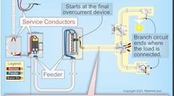
Microgrid systems operating in interactive mode can supply loads with the electric utility and other power production sources [Sec. 705.50], as shown in Fig. 3.
Microgrid systems operating in island (off-grid) mode can supply loads with other power production sources that have been disconnected from the electric utility.
Connections of the microgrid to the primary source must be per Sec. 705.11, Sec. 705.12, or Sec. 705.13. A microgrid interconnect device must comply with Sec. 705.70(1), (2), and (3). For example, it must have OCPDs for all power sources. Microgrid control systems (MCSs) must comply with Sec. 705.76(1) through (4). For example, an MCS must monitor and control transitions with the electric utility.
Keeping parallel straight
Remember that each parallel power source is interacting with the primary power source. This puts them on the same footing, in many ways. Carefully review the interconnections between these at every major step in design and installation.
Where you have choices, such as selecting one of three power production source equipment-to-utility connection methods in Sec. 705.11(A)(1) through (3), it’s not always clear how to proceed. The simplest of the three (connect to the supply side of the service conductors) brings drawbacks the other two choices do not. A new service could seem like a great choice, but where do you have room to put it? Making the correct choice for your facility starts with making a list of all issues with each choice.


