Article 215 covers the installation, conductor sizing, and overcurrent protection requirements for feeder conductors. The requirements for feeders have some similarities to those for branch circuits. But in some ways, feeders bear a resemblance to service conductors. It’s important to understand the distinct differences between these three types of circuits.
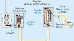
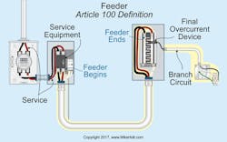
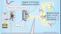
You can generally think of feeders as being the “middle set” of conductors in the power distribution scheme. At one end, you have the service equipment, the separately derived system, or other supply source. At the other end, you have the final branch-circuit overcurrent protection device (OCPD), as shown in Fig. 1. Feeders are the conductors between these two ends. Let’s make sure we have a clear idea of what those two ends are.
- Conductors past the final OCPD protecting the circuit and the outlet are branch-circuit conductors [Art. 100] and fall within the scope of Art. 210.
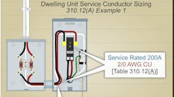
- Service conductors are the conductors from the service point to the service disconnect [Art. 100] and fall within the scope of Art. 230.
If there’s no serving electric utility — and the electrical power is derived from a generator or other on-site electric power source — then the conductors from the supply source are defined as feeders, and there are no service conductors.
It’s easy to become confused between feeder, branch-circuit, and service conductors, so it’s important to evaluate each installation carefully using the Art. 100 definitions. Otherwise, you risk applying the wrong set of NEC rules.
Minimum size of current-carrying conductors
You size feeder conductors differently from the way you size branch circuit conductors. With branch circuits, the OCPD size is known (e.g., it’s a 20A circuit), and you size the conductor accordingly. But with feeders, you determine the load and then size the conductor and OCPD accordingly. The “accordingly” part for the conductors means the feeder must be the larger of Sec. 215.2(A)(1)(a) and 215.2(A)(1)(b):
(a) The feeder conductor must have an ampacity (before ampacity correction and adjustment of) not less than 125% of the continuous load plus 100% of the noncontinuous load, based on the terminal temperature rating ampacities as listed in Table 310.15(B)(16) [110.14(C)(1)].
(b) The feeder conductor must have an ampacity, after ampacity correction and adjustment, of not less than the load to be served.
See Sec. 215.3 for the feeder OCPD sizing requirements for continuous and noncontinuous loads. The three Informational Notes in Sec. 215.2(A)(1) will help you correctly size your feeders. Informational Note 1: See Examples D1 through D11 in Informative Annex D.
Informational Note 2: To provide reasonable efficiency of operation of electrical equipment, feeder conductors should be sized to prevent a voltage drop not exceeding 3%. And the maximum voltage drop for the total of feeders and branch circuits shouldn’t exceed 5%.
Informational Note 3: See Sec. 210.19(A), Note 4, for voltage drop for branch circuits.
Now let’s look at a sample problem to illustrate the points outlined in Sec. 215.2(A)(1)(a).
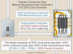
What size feeder conductors are required for a 100A continuous load and 100A noncontinuous load if the terminals are rated 75°C?
Because the load is 100A continuous at 125% — and the 100A noncontinuous load is at 100% — the feeder conductors must have an ampacity of at least 225A ([100A × 1.25] + [100A × 1.0] = 225A). According to the 75°C column of Table 310.15(B)(16) [110.14(C)(1)(b)], 4/0 AWG has an ampacity of 230A (Fig. 2).
Of course, there are exceptions to this rule:
Exception No. 1: If the assembly and OCPD are both listed for operation at 100% of their rating, then the conductors can be sized at 100% of the continuous and noncontinuous load. However, equipment suitable for 100% continuous loading is rarely available in ratings under 400A.
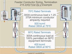
Exception No. 2: This exception is new with the 2017 NEC. A section of feeder conductors that terminates in a junction box (at each end) to 90°C terminals per Sec. 110.14(C)(2) is permitted to have an ampacity of at least 100% of the continuous and 100% of the noncontinuous load based on 90°C column of Table 310.15(B)(16) for 90°C conductor insulation. The 100% at 90°C feeder conductors are not permitted to extend into the supply or the load terminations to the feeder circuit.
Examples:
- A 400A feeder with 500kcmil conductors (rated 380A at 75°C) on supply and load terminals, with 400kcmil conductors (rated 380A at 90°C) between the supply and load ends (Fig. 3).
- A 1,200A feeder with three sets of 600kcmil conductors (420A at 75°C) on terminals with 500kcmil conductors (430A at 90°C) between supply and load ends.
Exception No. 3: Neutral conductors must have an ampacity of at least 100% of the continuous and noncontinuous load.
Minimum size of neutral
The feeder neutral conductor must be sized to carry the maximum unbalanced load per Sec. 220.61. It must not be smaller than listed in Sec. 250.122, based on the rating of the feeder OCPD.
Let’s work another example problem.
What size neutral conductor is required for a feeder consisting of 250kcmil ungrounded conductors and one neutral conductor protected by a 250A OCPD [see Sec. 215.2(A)(2)], where the unbalanced load is only 50A, with 75°C terminals?
Table 310.15(B)(16) and Sec. 220.61 permit an 8 AWG neutral conductor rated 50A at 75°C to carry the 50A unbalanced load. However, the neutral conductor isn’t permitted to be smaller than 4 AWG, as listed in Table 250.122, based on the 250A OCPD.
Sizing OCPDs
Feeder OCPDs must have a rating of not less than 125% of the continuous loads, plus 100% of the noncontinuous loads [215.3]. Exception: If the assembly and the OCPD are both listed for operation at 100% of its rating, then the OCPD can be sized at 100% of the continuous load.
What about feeders with a common neutral conductor? Up to three sets of 3-wire feeders or two sets of 4-wire or 5-wire feeders can use the same neutral conductor [215.4(A)]. The neutral conductor must be sized to carry the total unbalanced load for all feeders as determined in Art. 220 (see 220.61).
Equipment grounding conductor
Feeder circuits must include (or provide) an equipment grounding conductor (EGC) of a type listed in Sec. 250.118. This EGC must terminate in a manner so that branch-circuit EGCs can be connected to it, and installed per Sec. 250.134 [215.6].
Ground-fault protection of equipment
Each feeder disconnecting means rated 1,000A or more supplied by a 4-wire, 3-phase, 277/480V wye-connected system must be provided with ground-fault protection of equipment per Sec. 230.95 and Sec. 240.13 [215.10].
Two exceptions exist:
- The requirements don’t apply to a disconnecting means for a continuous industrial process if a disorderly shutdown will introduce increased or additional hazards.
- Equipment ground-fault protection isn’t required if ground-fault protection of equipment is provided on the supply side of the feeder and on the load side of the transformer supplying the feeder.
Ground-fault protection of equipment isn’t permitted for fire pumps [695.6(G)], and it’s not required for emergency systems [700.31] or legally required standby systems [701.26].
Conductor identification
An insulated feeder neutral conductor must be identified in accordance with Sec. 200.6 [215.12(A)]. The requirement that this conductor be insulated is new with the 2017 NEC.
EGCs can be bare. Individually covered or insulated EGCs sized 6 AWG and smaller must have a continuous outer finish either green or green with one or more yellow stripes [215.12(B) and 250.119].
Insulated equipment grounding conductors 4 AWG and larger can be permanently re-identified with green marking at the time of installation at every point where the conductor is accessible [250.119(A)].
If the premises wiring system contains feeders supplied from more than one voltage system, then each ungrounded conductor (at all termination, connection, and splice points) must be identified by phase or line and system in accordance with (a) and (b) [215.12(C)(1)]:
(a) Identification method. Identification can be by color coding, marking tape, tagging, or other means approved by the authority having jurisdiction.
(b) Posting of identification method. Such identification must be documented in a manner that’s readily available, or it must be permanently posted at each panelboard.
Although the NEC doesn’t require a specific color code for ungrounded conductors, electricians often use the following color system for power and lighting conductor identification:
• 120/240V, single-phase — black, red, and white
• 120/208V, 3-phase — black, red, blue, and white
• 120/240V, 3-phase — black, orange, blue, and white
• 277/480V, 3-phase — brown, orange, yellow, and gray; or, brown, purple, yellow, and gray
Avoiding feeder problems
The NEC provides the minimum size a feeder must be. It also recommends upsizing your conductors for voltage drop. However, there are many other factors to consider for a successful feeder installation, including selecting an insulation appropriate for the application and environment.
These materials are provided to us by Mike Holt Enterprises in Leesburg, Fla. To view Code training materials offered by this company, visit www.mikeholt.com/code
