So you go through all that work to correctly size your raceway, only to find out during the acceptance inspection that you have to replace some boxes and re-pull all of the conductors. The client’s acceptance engineer proved this with some calculations. “As a consolation, the new conductors will be easier for you to pull,” he told you.
Why must these boxes be so much bigger than the total raceway volume? How can you ensure you install boxes that are big enough without wasting money on boxes that are unnecessarily big?
The answer to the first question depends upon the type of box. An outlet box, for example, needs sufficient room to contain the connectors and provide sufficient free space for conductors, devices, and fittings. A pull box needs enough room to permit pulling conductors without bending them so much that you damage the insulation.
The answer to the second question is what Art. 314 is all about. To break it down even further, Sec. 314.16 deals with outlet, device, and junction boxes (as well as conduit bodies) for conductor sizes between 18 AWG and 6 AWG. Section 314.28 is used for junction and pull boxes for conductor sizes 4 AWG and larger.
What’s the volume?
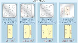
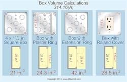
The volume of a box is the total volume of its assembled parts, including plaster rings, raised covers, and extension rings. The total volume includes only those parts that are marked with their volume in cubic inches [314.16(A)] or included in Table 314.16(A) (Fig. 1).
When all of the conductors in an outlet box are the same size (insulation doesn’t matter), you can use Table 314.16(A) to determine the number of conductors permitted in the box or the box size required for the given number of conductors.
Table 314.16(A) doesn’t consider switches, receptacles, luminaire studs, luminaire hickeys, internal cable clamps, or equipment grounding conductors. If the box contains any of these, you must make allowances. Fortunately, the NEC tells you what those allowances are. What you do is take each step of 314.16(B)(1) through (B)(5), then add the results together to determine the total volume required.
Does it count?
When using Table 314.16(B), you don’t count all things the same way. Count these items as a single volume:
• Each unbroken conductor that runs through a box.
• Each conductor that terminates in a box.
• One or more internal cable clamps, based on the largest conductor that enters the box.
• Each luminaire stud or luminaire hickey, based on the largest conductor that enters the box.
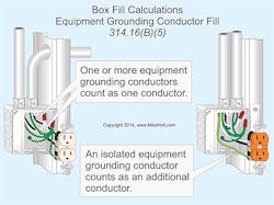
• All (not each) equipment grounding conductors in a box, based on the largest equipment grounding conductor that enters the box (Fig. 2).
• All insulated equipment grounding conductors for receptacles having insulated grounding terminals (isolated ground receptacles) [250.146(D)].
Count these items as a double volume:
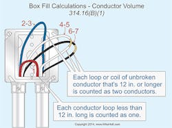
• Each loop or coil of unbroken conductor that’s at least twice the minimum length required (12 in.) for free conductors in Sec. 300.14 (Fig. 3).
• Each single-gang device yoke (regardless of the physical size of the device), based on the largest conductor that terminates on the device.
• Each multi-gang device yoke (for each gang), based on the largest conductor that terminates on the device.
Don’t count these items:
• Cable connectors that have their clamping mechanism outside the box.
• Equipment grounding conductors and up to four 16 AWG and smaller fixture wires if they enter the box from a domed luminaire or similar canopy, such as a ceiling paddle fan canopy.
• Wire connectors, cable connectors, raceway fittings, and conductors that originate and terminate within the outlet box (e.g., equipment bonding jumpers and pigtails).
• The plaster ring if not stamped with its cubic-inch volume.
Sizing outlet boxes
To size an outlet box when the conductors are different sizes
(insulation isn’t a factor), follow these steps:
Step 1: Determine the number and size of conductor equivalents in the box.
Step 2: Determine the volume of the conductor equivalents from Table 314.16(B).
Step 3: Use the results of steps 1 and 2 in Table 314.16(A).
Sizing pull boxes and junction boxes
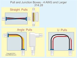
When insulated conductors 4 AWG or larger enter a pull box or junction box, you must calculate the box size. And the calculation depends upon the type of pull (Fig. 4):
1. A straight-pull is when conductors enter one side of a box and leave through the opposite wall. The distance between those walls must be at least eight times the trade size of the largest raceway [314.28(A)(1)].
2. An angle pull is when conductors leave through a wall that’s 90° from the wall they came in on. The distance between the entry wall and its opposite wall must be at least six times the trade size of the largest raceway, plus the sum of the trade sizes of the remaining raceways on the same wall and row [314.28(A)(2)].
3. When a conductor enters and leaves from the same wall, that’s a U-pull. The distance from that wall to its opposite wall must not be less than six times the trade size of the largest raceway, plus the sum of the trade sizes of the remaining raceways on the same wall and row [314.28(A)(2)].
You can combine all of these requirements into a three-step process:
Step 1: Calculate the HORIZONTAL distance(s):
• Left to right straight calculation
• Right to left straight calculation
• Left to right angle or U-pull calculation
• Right to left angle or U-pull calculation
Step 2: Calculate the VERTICAL distance(s):
• Top to bottom straight calculation
• Bottom to top straight calculation
• Top to bottom angle or U-pull calculation
• Bottom to top angle or U-pull calculation
Step 3: Calculate the distance between raceways enclosing the same conductors.
Three other factors in this situation affect the minimum box size, also:
1. If any splices are in the box, then the distance to the opposite wall from where the raceways enter must be at least six times the trade size of the largest raceway, plus the sum of the trade sizes of the remaining raceways on the same wall and row.
2. Where there are multiple rows of raceway entries, calculate each row individually, and use the row with the largest distance.
3. The distance between raceways enclosing the same conductor must be at least six times the trade size of the largest raceway (measured nearest edge-to-nearest edge) [314.28(A)(2)]. But when conductors enter an enclosure with a removable cover, the distance from where the conductors enter to the removable cover must be at least the bending distance listed in Table 312.6(A) for one conductor per terminal.
And there’s one more factor. Some specialty cables have a very large bend radius; you might need a larger box than your Art. 314 calculations indicate.
Junction box example
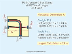
A junction box contains two trade size 3 raceways on the left side and one trade size 3 raceway on the right side. The conductors from one of the trade size 3 raceways on the left wall are pulled through the trade size 3 raceway on the right wall. The conductors from the other trade size 3 raceways on the left wall are pulled through a trade size 3 raceway at the bottom of the pull box. It is helpful to draw out the problem. See if you can correctly answer these three questions:
Question 1: What’s the horizontal dimension of this box? (Fig. 5)
Left to right straight pull = 8 × 3 in. = 24 in.
Right to left straight pull = 8 × 3 in. = 24 in.
Left to right angle pull = (6 × 3 in.) + 3 in. = 21 in.
Right to left angle pull = no calculation
Therefore, the answer is 24 in.
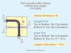
Question 2: What’s the vertical dimension of a junction box having a trade size 3 raceway on the bottom of the junction box with no raceways on the top of the box (Fig. 6)?
Top to bottom straight pull = no calculation
Bottom to top straight pull = no calculation
Top to bottom angle pull = no calculation
Bottom to top angle pull = 6 × 3 in. = 18 in.
Therefore, the answer is 18 in.
Question 3: What’s the minimum distance between the two trade size three raceways containing the same conductors?
This is pretty straightforward. The correct answer is: 6 × 3 in. = 18 in.
Thinking inside the box
Boxes serve many functions that raceways do not, so they require much more space than simply the sum of the raceway volumes. A single box with insufficient interior space can cause the whole raceway system to fail inspection or, worse, cause the circuit to catastrophically fail while in operation.
Outlet box sizing applies to every outlet box. But junction box and pull box calculations are required only when the conductors are 4 AWG or larger; straight pulls, angle pulls, and U-pulls all affect how big that box must be.
However, other factors can determine the box size. For example, a specialty cable has a 40-in. bend radius so the box must be large enough to permit installing that cable without exceeding that radius.
Holt is the owner of Mike Holt Enterprises, Inc. in Leesburg, Fla. He can be reached at www.mikeholt.com.
