Among the ways service conductor requirements differ from those for branch circuit and feeder conductors is service conductors for one structure can’t pass through the interior of another structure [230.3]. You also apply different rules, depending on whether a service conductor is inside or outside a structure. When are they “outside” as opposed to “inside?” The answer seems simple at first glance, but the obvious answer may be wrong.
For example, you’re standing 6 ft inside a building directly above the conductors. So “obviously,” those conductors are inside the building. But the “inside” extends into the earth only a short distance. For example, if you’re standing on a 3-in. concrete slab, the conductors below you are considered outside of the building [230.6].
What’s a service conductor?
To correctly apply the requirements of Art. 230 (see The Eight Parts of Article 230), you must understand what a service conductor is and how it relates to the overall installation. Three Art. 100 definitions help with that understanding:
1) Service conductors. The conductors from the service point to the service disconnecting means. Conductors upstream of the service point aren’t service conductors — they’re electric utility conductors (service drop or service lateral).
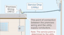
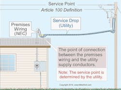
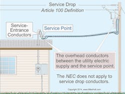
2) Service point. This is the point of connection between the serving electric utility and the premises wiring. This is where the requirements in Art. 230 really begin (Fig. 1).
3) Service equipment. The necessary equipment, usually consisting of circuit breakers or switches and fuses and their accessories, connected to the load end of service conductors at a building or other structure, and intended to constitute the main control and cutoff of the electrical supply. Service equipment doesn’t include individual meter socket enclosures [230.66].
Service conductors originate at the serving electric utility (service point) and terminate on the line side of the service disconnecting means. If the conductors come from any source other than the electric utility, then they’re not service conductors. Keep these concepts in mind when applying Art. 230 so you don’t inadvertently treat feeders as service conductors or vice-versa.
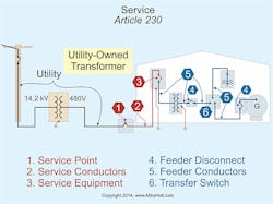
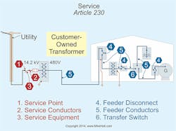
It also helps to know where the service/feeder boundary is located. Conductors on the load side of service equipment are feeder or branch circuit conductors. You install these in accordance with Art. 215 and Art. 210, respectively. If they’re outside, they must also comply with Art. 225.
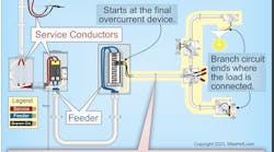
Feeder conductors (Fig. 2 and Fig. 3) include:
• Secondary conductors from customer-owned transformers.
• Conductors from generators, UPS systems, or PV systems.
• Conductors to remote buildings or structures if the building contains a panel.
Outside
Let’s look closer at that “outside the building” issue, as it’s a common source of confusion. Conductors are considered outside of a building when they’re installed [230.6]:
1) Under 2 in. (or more) of concrete beneath a building/structure.
2) Within a building/structure in a raceway encased in 2 in. (or more) of concrete or brick.
3) In a vault that meets the construction requirements of Art. 450, Part III.
4) In a raceway under 18 in. (or more) of the earth beneath a building/structure.
5) Within rigid or intermediate metal conduit that passes directly through an eave but not a wall of a building.
With the 2014 NEC, item 5 has been revised to clarify that the conductors inside a raceway mast are considered outside the building when they travel vertically through the eaves of a building.
The word “mast” was removed to clarify an issue. A mast could be a large piece of wood with SE cable attached to it. Obviously, such a mast doesn’t provide the protection or the safety given by rigid or intermediate metal conduit.
The NEC is now clear that this allowance applies to a short length of raceway that travels vertically through the eave. There have been installations where the raceway penetrates the eave, travels horizontally for 10 ft or more inside of the eave, then turns vertically to penetrate the roof. This type of installation wasn’t intended under previous editions of the NEC and is now specifically discussed.
Overhead
The 2011 NEC contained many changes to “service” related terms such as service point, service drop, and overhead service conductors in Art. 100 and Art. 230. With so many changes, some instances of incorrect usage were bound to remain.
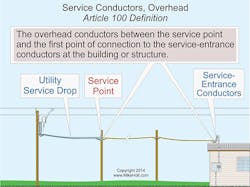
“Service-drop conductors” is one such term. These are electric utility conductors and therefore aren’t regulated by the NEC (Fig. 4). Section 230.26 has been revised to use the correct term — “overhead service conductors” [see Art. 100 definition (Fig. 5)] — as those are the conductors regulated by the NEC.
The point of attachment for overhead service conductors must be at least 10 ft above the finished grade. And you must locate it so the minimum clearances required by 230.9 and 230.24 can be maintained if the overhead conductors are service conductors [230.26].
Be aware that you might need to raise the point of attachment for overhead service conductors so they comply with the clearances from building openings required by 230.9 and from other areas by 230.24. Again, this only applies if the conductors in question are on the load side of the service point; otherwise, they aren’t service conductors — they’re electric utility conductors.
Strong masts
When you install masts to support overhead service conductors or service drops, pay attention to the requirements for strength and attachment [230.28]:
• Strength. If you use a mast for overhead conductor support, it must have adequate mechanical strength, or it must have braces or guy wires to withstand the strain caused by the conductors. Conduit hubs must be identified for use with a mast.
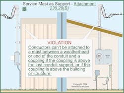
• Attachment. Conductors can’t be attached to a mast between a weatherhead or end of the conduit and a coupling if the coupling is above the last conduit support, or if the coupling is above the building or structure (Fig. 6).
Note that Sections 810.12 and 820.44(C) specify you can’t attach aerial cables for radio, TV, or CATV to the service mast. Also:
• 810.12 prohibits antennas from being attached to the service mast.
• 800.133(B) and 830.133(B) prohibit broadband communications cables from being attached to raceways, including a service mast.
Unfortunately, the NEC has never provided much guidance on the strength requirements for overhead masts. While it still requires some judgment (what does “adequate strength” mean?), the new language regarding couplings provides at least some prescriptive requirements for inspectors to hang their hats on and for installers to follow.
Previous editions of the NEC stated that all fittings used in a mast must be identified for such use. This was problematic because some fittings, such as rigid couplings, aren’t specifically identified for such use (see the UL White Book, category DWTT), although they’re certainly strong enough to be used. Conduit hubs that meet the requirements are marked on either the fittings themselves or on the carton in which they come as being suitable for use on a mast.
Some local codes require a minimum trade size 2 rigid metal conduit for the service mast. In addition, many electric utilities contain specific requirements for the installation of the service mast.
Sizing requirements for service conductors. Service-entrance conductors must have sufficient ampacity for the loads to be served, per Parts III, IV, or V of Art. 220 [230.42]. The ampacity must not be less than 230.42(A)(1), (A)(2), or (A)(3).
1) 125% of the continuous loads, plus 100% of the noncontinuous loads. See 215.3 for the sizing requirements of feeder overcurrent devices for continuous and noncontinuous loads.
2) The sum of the noncontinuous load plus the continuous load (at 100%) after the application of any adjustment of correction factors.
3) 100% of the continuous and noncontinuous load, if the conductors terminate to an overcurrent device listed for 100% of its rating.
Let’s take a look at a sample problem to make sure you understand this concept.
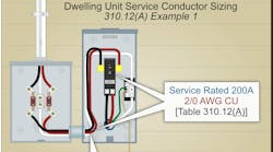
What size service-entrance conductors do you need for a 200A continuous 3-phase load, if the terminals are rated 75°C?
Since the load is 200A continuous, the service-entrance conductors must have an ampacity not less than 250A (200A × 1.25). According to the 75°C column of Table 310.15(B)(16), 250kcmil conductors are suitable because they have an ampere rating of 255A at 75°C. The 75°C column is used because of the requirements of 110.14(C)(1)(b).
What about the service neutral conductor? You must size it to carry the maximum unbalanced load per 220.61 [230.42(C)]. Don’t size it smaller than required by 250.24(C), which refers to the new Table 250.102(C)(1). Why this minimum size? To ensure that it has sufficiently low impedance and current-carrying capacity to safely carry fault current, it must facilitate the operation of the overcurrent device.
From an engineering standpoint, going larger than this has almost no downside, and the change in wire size is cheap insurance against future increases in the unbalanced loads.
Avoiding costly mistakes
Fixing Code violations after installing the service conductors is often very costly — much more so than fixing similar mistakes with feeder or branch circuit conductors. Pay careful attention to how you define the indoor/outdoor boundary for those conductors, and you’ll avoid a major trap.
To avoid falling short of the “adequate strength” requirement, conduct mechanical strength calculations (e.g., cantilever calculations) and specify masts that leave no doubt they meet that requirement.
SIDEBAR: The Eight Parts of Article 230
Part I. General
Part II. Overhead Service Conductors
Part III. Underground Service Conductors
Part IV. Service-Entrance Conductors
Part V. Service Equipment
Part VI. Disconnecting Means
Part VII. Overcurrent Protection
Part VIII. Services over 1,000V
