The use of structural metal as a grounding electrode is an issue that has been revised during several recent Code cycles. The 2011 NEC has once again revisited the rule explaining when a structural metal building frame can serve as a grounding electrode.
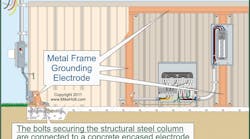
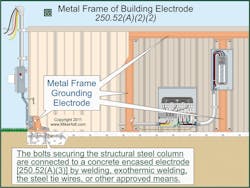
When the structural metal is in direct earth contact for 10 ft or more, with or without concrete encasement, it is considered to be connected to the earth and is acceptable for use as a grounding electrode [250.52(A)(2)(1)]. The hold-down bolts securing the structural steel column that are connected to a concrete-encased electrode are considered to provide a satisfactory earth connection [250.52(A)(2)(2)]. The concrete-encased electrode must comply with the requirements of 250.52(A)(3), and the hold-down bolts must be connected to the concrete-encased electrode by means of welding, exothermic welding, the usual tie wires used to secure the rebar in a footing, or other approved means (Fig. 1).
The 2011 NEC no longer allows the structural metal to serve as a grounding electrode when supplemented by a ground rod.
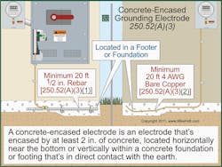
The requirements for a concrete-encased electrode, commonly called a "Ufer Ground" are included in 250.52(A)(3). This is an electrode developed by using electrically conductive reinforcing bars or bare copper conductors not smaller than 4 AWG at least 20 ft in length. These rebar or this conductor must be encased by at least 2 in. of concrete and located inside the concrete footing or foundation that is in direct contact with the earth (Fig. 2).
A new informational note has been added to 250.52(A)(3) to clarify how a concrete-encased electrode is impacted by the use of insulation, vapor barriers, films, or similar items that separate the concrete from the earth. This note explains that when such materials are encountered that insulate the concrete from the earth, the "direct contact" with the earth required for the use of a concrete encased electrode has been lost. In such a case, the concrete-encased electrode is not present, and another suitable electrode must be used. This is an important consideration in view of some of the modern building methods in use.
Section 250.52(A)(5) contains the provisions for the use of rod and pipe electrodes. The minimum length for rod and pipe electrodes is 8 ft, and the minimum size for a rod is 5/8 in. in diameter, unless it is listed. Previously, the Code also included a minimum diameter for listed rods. This dimension has been removed for listed rods, since this is an issue for the testing lab, not for the NEC.
A plate electrode that exposes at least 2 sq ft. of surface to exterior soil is permitted as a grounding electrode. A 2011 Code change to 250.52(A)(7) clarifies that plate electrodes must be conductive. The electrode must be a bare or conductively coated iron or steel plate at least ¼ in. thick, or a solid uncoated nonferrous metal plate at least 0.06 in. thick.
25 ohms
A long-standing rule says that a ground rod or pipe or plate electrode must have a resistance to earth of 25 ohms or less, or be supplemented by an additional electrode [250.53(A)(2)]. These requirements were spread out in several different Code sections until the 2011 edition. The Code requirements are now easier to understand and match the standard industry practice of driving two ground rods instead of testing the resistance of a single driven rod. The allowance to use only a single rod, pipe, or plate electrode when a resistance of 25 ohms or less to ground is obtained is now written as an exception to [250.53(A)(2)].
When using multiple rod, pipe, or plate electrodes to meet the requirements of 250.53, they must be spaced at least 6 ft apart. The Informational Note following 250.53(A)(3) explains that this increases the efficiency in paralleling. A revision to this Note now provides additional guidance as to what the spacing should be. The revised Note states that the spacing between driven rods should be at least twice the length of the longer of the two rods.
Grounding electrode conductor (GEC) installation
The balance of Part III of Art. 250, beginning with 250.62, contains requirements for the grounding electrode conductor (GEC). Section 250.64(B) was updated to include some new raceway systems that have been added to the NEC in recent editions. It's now clear that both PVC conduit and RTRC conduit can be used for protecting the GEC, in addition to the other raceways that the Code already specifically mentioned. Another minor change took place in regard to the use of metal elbows in nonmetallic raceway (see SIDEBAR: Elbow Below).
Although the definition of "tap conductor" is in 240.2 — and therefore should be used only for conductors described in Art. 240 — most people in the industry think of an ungrounded conductor when they read the phrase "tap conductor." To avoid this confusion, and provide language consistency, the term "tap conductor" in Part III has been replaced with "grounding electrode conductor tap." Some other grounding related terms were clarified as well (see SIDEBAR: Coming to Terms).
The NEC has long required that ferrous metal raceways containing the GEC be bonded at each end to reduce the effects of "inductive choke" on the conductors. The Code now includes more specifics on how to do this. The bonding method must be in compliance with 250.92(B) at service equipment locations. For other than service equipment locations, 250.92(B)(2) through (B)(4) must be followed to meet this requirement [250.64(E)].
Nonferrous metal raceways, such as aluminum rigid metal conduit, enclosing the GEC are not required to meet the "bonding each end of the raceway to the GEC" provisions of this section.
The effectiveness of a grounding electrode is significantly reduced if a ferrous metal raceway containing a GEC isn't bonded to the GEC at each end. This is because a single conductor carrying high-frequency induced lightning current in a ferrous raceway causes the raceway to act as an inductor. That severely limits (chokes) the current flow through the GEC. ANSI/IEEE 142, "Recommended Practice for Grounding of Industrial and Commercial Power Systems" (Green Book) states: "An inductive choke can reduce the current flow by 97%."
To save time and effort, install the GEC exposed if it's not subject to physical damage [250.64(B)], or enclose it in PVC conduit suitable for the application [352.10(F)].
Part VI
The changes to the requirements for equipment grounding (bonding) begin with 250.118. These changes provide consistency with defined terms and address the vibration of equipment connected to flexible raceways.
The effective ground fault path is an intentionally constructed low-impedance conductive path designed to carry fault current from the point of a ground fault on a wiring system to the electrical supply source. Its purpose is to quickly remove dangerous voltage from a ground fault by opening the circuit overcurrent device [250.2].
The NEC has required the installation of an EGC of the wire type in flexible metal conduit (FMC) or liquidtight flexible metal conduit (LFMC) that terminate to equipment needing flexibility after installation, but previously has not addressed the issue of vibration.
It is possible that an unusually high amount of vibration could compromise the integrity of flexible metal conduit or its fittings at termination points, reducing its ability to act as an EGC. A change to 250.118(5)(d) addresses this and requires an EGC of the wire type where vibration or the need for flexibility for movement is a factor for FMC. The 2011 NEC also contains a similar change in the requirements for LFMC [250.118(6)(e)].
Use of equipment grounding conductors (EGCs)
The purpose of the grounding electrode conductor (GEC) is to help direct lightning induced energy to the earth. But the purpose of an equipment grounding conductor (EGC) is to provide a low-impedance ground-fault current path to the source to operate overcurrent devices in the event of a ground fault.
These conductors serve entirely different purposes, so it is understandable that their sizing requirements differ. The sizing of an EGC depends on 250.122, while GECs are sized according to 250.66.
Because these conductors have different rules, different sizing requirements, and different installation requirements, the 2011 NEC added 250.121 to clarify that an EGC must not be used as a GEC.
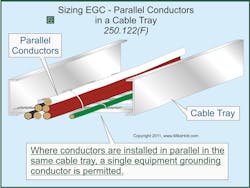
If circuit conductors are installed in parallel in separate raceways as permitted by 310.10(H), an equipment grounding conductor must be installed for each parallel conductor set. Where conductors are installed in parallel in the same raceway or cable tray, a single equipment grounding conductor is permitted [250.122(F)]. In the 2011 NEC, 250.122(F) was changed to help clarify the fact that one EGC, properly sized, may be installed in the raceway with multiple sets of parallel ungrounded and grounded conductors (Fig. 3).
Each EGC must be sized per Table 250.122, based on the rating of the circuit overcurrent device, but it's not required to be larger than the circuit conductors [250.122(A)].
In cable trays, single conductor EGCs can be insulated, covered, or bare. But they must be 4 AWG and larger [392.10(B)(1)(c)].
As you can see, the changes to Art. 250 were extensive. However, most of the changes clarify existing technical concepts, rather than replacing them with new ones. The goal was to clear up common misunderstandings and prevent common misapplications.
The EGC clarification is an example of that. It's also an example of solving the grounding confusion in general. If it’s a load side application, you'll be bonding (such as running an EGC), not grounding, which occurs on the supply side.
SIDEBAR: Elbow Below
Previous NEC editions have recognized that metal elbows in an underground system of rigid nonmetallic conduit are not required to be grounded when isolated from possible contact by a minimum cover of 18 in. With recent changes in the Code allowing for more nonmetallic raceways, this rule now says that metal elbows in an underground system of any nonmetallic raceway need not be grounded. It's the Exception note to 250.80.
SIDEBAR: Coming to Terms
Previous NEC editions used the undefined term "ground return path," instead of "ground-fault current path." Now Art. 250 Part VI replaces the undefined term with a defined one.
The 2011 NEC also deleted the very general term "grounding conductor," replacing it with more accurate terminology. For example, in some places it was replaced by use of the term "equipment grounding conductor," in other places by the term "grounding electrode conductor" resulting in the use of wording much more specific to the application.
