In just milliseconds, a voltage surge can destroy valuable equipment or even bring an entire facility down; thus, protection against transient voltage spikes is important. Hard-wired transient protection devices are covered by either Art. 280 (above 1kV) or Art. 285 (1kV or less). Art. 280 refers to them as surge arresters, while Art. 285 refers to them as surge-protective devices (SPDs).
Most Art. 285 surge arresters operate by "clipping off" the highest level of voltage and diverting it away from the load. In this manner, the voltage on the conductor is limited to a predetermined level. The spark gap arrester is a simple device and an example of a surge arrester. Although it's an Art. 280 device, describing its operation helps us understand the operation of the surge arresters covered by Art. 285.
One lead of the spark gap arrester is on the protected conductor; the other is on the conductor of an alternate path. At the arrester, an "air gap" (actually, it's not air but some inert gas) separates these leads. The gas normally provides such a high impedance that current flow is nearly zero (per Kirchhoff's Law, some current will flow through the gas). But when voltage hits a certain level, current jumps through the gas. Subsequently, the gas acts as a short circuit. The gas will continue to shunt current until voltage drops to a level closer to normal.
Article 285 surge-protective devices don't use a gas and don't have the short-circuit effect. Instead, a solid state device, such as a metal oxide varistor (MOV) or silicon avalanche suppression diode (SASD), "switches on" at a certain voltage. Unlike the spark gap arrester, these devices conduct only the overvoltage portion of the electricity. The effect is called "voltage clamping," and they have to clamp within a limited range of voltage.
That's where transient voltage surge suppressors (TVSSs) come in. A basic TVSS cascades a series of MOVs to render the spike progressively smaller until it's no longer a threat. Thus, you can install one device that will handle the entire voltage range of the spike at a given location. However, a TVSS may do more than that, because the diversion technique isn't the only method of dealing with power spikes.
Although it's true that diversion devices tend to dissipate much of the transient energy as heat, they do not eliminate transient power spikes. They primarily reduce the voltage levels and incidentally reduce the energy levels, which isn’t always sufficient protection. It may also be necessary to add filtering to the protection scheme. Filtering devices do not divert the transients, but use inductive and capacitive elements to absorb them. Filtering devices may be incorporated into a TVSS, which is subsequently covered by Art. 285.
Hardware. When planning an SPD installation, look at your hardware options. For example, you must decide which performance specifications you need for each device at a given point of protection. It's tough to sort through all this and come up with a well-engineered solution. But it's even tougher to go back and do it over if you didn't comply with the following SPD requirements at the outset:
1) Where used, the SPD must be connected to each ungrounded conductor of the circuit [285.4].
2) SPDs must be listed [285.5] for the intended use. UL 1449, “Standard for SPDs,” clearly states that these units "limit the maximum amplitude of transient voltage surges to specified values."
3) Each SPD must be marked with its short-circuit current rating, and a hazardous condition is present if the SPD short-circuit current rating is less than the available fault current.
Installation. SPDs aren't essential to the prevention of fires, so the NEC doesn't require anyone to install them. However, incorrect installation poses a hazard. Therefore, if you install SPDs, you must install them per Art. 285. Don't install SPDs in any of the following applications [285.3]:
• Circuits that exceed 1kV.
• Ungrounded systems, impedance grounded systems, or corner-grounded delta systems, unless listed specifically for use on these systems.
• Where the voltage rating of the SPD is less than the maximum continuous phase-to-ground voltage available at the point of connection.
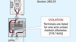
Avoid unnecessary bends in SPD conductors [285.12], and don't make the conductors any longer than necessary. You can connect only one conductor to a terminal, unless the terminal is identified for multiple conductors [110.14(A)] (Fig. 1).
Three ratings. From highest energy level to lowest, SPDs may be rated Type 1, Type 2, or Type 3 [285.1, FPNs 1 and 2]. The energy level is a device safety rating based on several characteristics. SPD Type is not a performance rating. The NEC is concerned only with the safety aspects; therefore, it provides limitations on where you can install an SPD based on its Type.
Type 1 SPD — You can install Type 1 SPDs [285.23] on the supply side of service equipment [230.82(4)] (Fig. 2). It's also common to install them on the load side of service equipment per 285.24, based on the energy levels encountered there. You must connect them to one of the following:
(1) Service neutral conductor.
(2) Grounding electrode conductor.
(3) Grounding electrode for the service.
(4) Equipment grounding terminal in the service equipment.
Type 2 SPD — You can install Type 2 SPDs [285.24] on the:
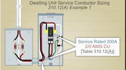
• Load side of service equipment per 285.24 (Fig. 3).
•The load side of the building/structure overcurrent device.
• The premises wiring of the separately derived system.
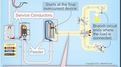
Type 3 SPD — You can install Type 3 SPDs [285.25] on the load side of a branch-circuit overcurrent device up to the equipment served. But only if the connection is a minimum 30 ft of conductor distance from the service or separately derived system disconnect.
Conductors. Conductors for SPDs must be at least 14 AWG copper or 12 AWG aluminum. You can connect an SPD between any two circuit conductors and all grounding connections must conform to Art. 250, except as noted in Art. 285.
Permanent transient protection. A good transient protection system that includes a properly specified SPD scheme installed per Art. 285 can easily pay for itself with one power event. The economics for installing such a system are compelling for almost any facility. That doesn't mean you can just install it and forget about it. By the nature of what they are called upon to do, SPDs tend to lead fairly short lives compared to other electrical equipment.
While you can easily tell when a transformer blows or a motor fails, an SPD failure doesn't announce itself by shutting down production. An SPD doesn't operate under normal conditions; it operates under abnormal conditions. For this reason, a failure goes unnoticed when everything is going well (unless you have SPD instrumentation to make it noticed).
The NEC doesn't require you to conduct preventive maintenance, monitoring, or testing on your SPDs. Nor does it require you to test them after a storm or after a known power event.
From an operational viewpoint, however, these measures allow you to ensure your SPDs will provide the protection that justified their installation in the first place. "Testing by transient" is not a cost-effective way to maintain SPDs.


