Thank you for visiting one of our most popular classic articles. If you’d like to see updated information on this topic, please check out this recently published article, Load Calculations — Part 2. |
Based on the 2002 National Electrical Code.
Part 1 of this two-part series explained how to size overload protection devices and short-circuit and ground-fault protection for motor branch circuits. Understanding the key point of that article, which was that motor overload protection requires separate calculations from short-circuit and ground-fault protection, clears up a common source of confusion and a point of error. But another source of confusion arises when it comes to sizing short-circuit and ground-fault protection for a feeder that supplies more than one motor. Let's look again at branch-circuit calculations and then resolve the feeder issues so your calculations will always be correct.
Branch-circuit conductors and protection devices
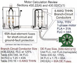
Per 430.6(A), branch-circuit conductors to a single motor must have an ampacity of not less than 125% of the motor full-load current (FLC) as listed in Tables 430.147 through 430.150. To illustrate this, let's size the branch-circuit conductors (THHN) and short-circuit ground-fault protection device for a 3-hp, 115V, single-phase motor. The motor FLA is 31A, and dual-element fuses for short-circuit and ground-fault protection are in use (Fig. 1).-
Per Table 430.148, the FLC current is 34A.
-
34A×125%=43A.
-
Per Table 310.16 (60°C terminals [110.14(C)(1)(a)]), the conductor must be a 6 AWG THHN rated 55A.
Per the motor FLC listed in Table 430.52, size the branch-circuit short-circuit and ground-fault protection devices by using multiplication factors based on the type of motor and protection device. When the protection device values determined from Table 430.52 don't correspond with the standard rating of overcurrent protection devices listed in 240.6(A), you must use the next higher overcurrent protection device. To illustrate this, let's use the same motor as in the previous example.
- Per 240.6(A), multiply 34A×175%
- You need a 60A dual-element fuse.
To explore this example further, see Example No. D8 in Annex D of the 2002 NEC. Once you've sized the motor overloads, branch-circuit conductors, and branch-circuit protective devices, you're ready to move on to the next step.
Motor feeder conductor calculations
From 430.24, you can see that conductors that supply several motors must have an ampacity not less than:
-
125% of the highest-rated motor FLC [430.17], plus
-
The sum of the FLCs of the other motors (on the same phase), as determined by 430.6(A), plus
-
The ampacity required to supply the other loads on that feeder.
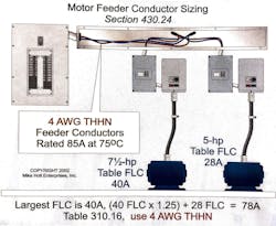
Example No. 1. For what ampacity must you size the feeder conductor if it supplies the following two motors? The terminals are rated for 75°C.
-
One 7.5-hp, 230V (40A), single-phase motor
-
One 5-hp, 230V (28A), single-phase motor
(a) 50A
(b) 60A
(c) 70A
(d) 80A
Let's walk through the solution.
-
The largest motor is 40A.
-
40A×1.25+28A=78A.
-
80A is the closest selection that's at least 78A.
What size conductor would give us this ampacity?
(a) 2 AWG
(b) 4 AWG
(c) 6 AWG
(d) 8 AWG
Per Table 310.16, a 6 AWG conductor rated at 75°C provides 65A of ampacity, so it's too small. However, a 4 AWG conductor provides 85A of ampacity, which will accommodate the necessary 78A. Therefore, you need to size this feeder conductor at 4 AWG.
Next, we have to determine what size overcurrent protection device (OCPD) we must provide for a given feeder.
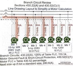
- Three 1-hp, 120V, single-phase motors
- Three 5-hp, 208V, single-phase motors
- One wound-rotor, 15-hp, 208V, 3-phase motor
Refer to 240.6(A), 430.52(C)(1), Table 430.148, and Table 430.52. Start by determining the ampacities required for each size of motor, then walk through each step until you arrive at the correct OCPD size.
-
1-hp motor: FLC is 16A.
16A×250%=40A -
5-hp motor: FLC is 30.8A.
30.8A×250%=77A (Next size up is 80A.) -
15-hp motor: FLC is 46.2A.
46.2A×150% (wound-rotor) 569A (Next size up is 70A.)
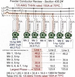
Now, let's look at the feeder conductor. Conductors that supply several motors must have an ampacity of not less than 125% of the highest-rated motor FLC (430.17), plus the sum of the other motor FLCs [430.6(A)] on the same phase (Fig. 4).
Continuing with this example, add up all the ampacities, multiplying the highest-rated motor by 125%. Thus:
-
(46.2A×1.25)+30.8A+30.8A+16A=136A.
You must provide the feeder with a protective device with a rating or setting not greater than the largest rating or setting of the branch-circuit short-circuit and ground-fault protective device (plus the sum of the full-load currents of the other motors of the group) [430.62(A)]. Remember, motor feeder conductors must be protected against the overcurrent that results from short circuits and ground faults but not those that result from motor overload.
When sizing the feeder protection, be sure to include only the motors that are on the same phase.
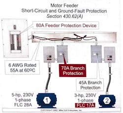
Refer to Fig. 5 for this sample motor feeder protection calculation.
Example No. 3. What size feeder protection (inverse-time breaker) do you need for the following two motors?
- 5-hp, 230V, single-phase motor
- 3-hp, 230V, single-phase motor
(a) 30A breaker
(b) 40A breaker
(c) 50A breaker
(d) 80A breaker
Let's walk through the solution.
- A 5-hp motor FLC is 28A.
- A 3-hp motor FLC is 17A.
Step 2: Size the branch-circuit protection per the requirements of 430.52(C)(1), Table 430.52, and 240.6(A)
-
5-hp: 28A×2.5=70A
-
3-hp: 17A×2.5=42.5A (Next size up is 45A.)
Step 3: Size the feeder conductor per 430.24(A).
-
The largest motor is 28A.
-
(28A×1.25)+17A=52A
-
Table 310.16 shows 6 AWG rated 55A at 60°C as the smallest conductor with sufficient ampacity.
Step 4: Size the feeder protection per 430.62.
-
It must not be greater than the 70A protection of the branch circuit plus the 17A of the other motor, which is the total of all loads on that feeder.
-
70A+17A=87A
Choose the next size down, which is 80A.
How can you be safe if you're selecting the next size down instead of the next size up? Remember, you've already accounted for all the loads, and the NEC requires that you not exceed the protection of the branch circuit. Again, keep in mind that you aren't calculating for motor overload protection. Motor calculations are different from other calculations. With motor feeders, you're calculating for protection from short circuits and ground faults, only — not overload.
Putting it all together
Motor calculations get confusing if you forget there's a division of responsibility in the protective devices. To get your calculations right, you must separately calculate the motor overload protection (typically near the motor), branch-circuit protection (from short circuits and ground faults), and feeder-circuit protection (from short circuits and ground faults). Remember that overload protection is only at the motor.
Any time you find yourself confused, just refer to NEC Figure 430.1. It shows the division of responsibility between different forms of protection in motor circuits. Example D8 in Annex D of the 2002 NEC illustrates this with actual numbers. Keeping this division of responsibility in mind will allow you to make correct motor calculations every time.
