Thirty to 35 years ago, distributed control systems (DCSs), along with new analog and digital instrument systems, were in their infancy. Programmable logic controllers (PLCs) and other electronic instrumentation were very susceptible to noise when connected to the plant grounding electrode system. In the early days, some manufacturers of DCS systems mistakenly assumed that creating a separate, isolated grounding electrode system was the answer to their unwanted, noisy grounding issues. Creating a separate, isolated grounding electrode system at the remote instrument enclosure (RIE) or control rooms for electronic grounding was, and is still, not acceptable per the National Electrical Code (NEC).
Per Sec. 250.50 of the 2014 NEC, all grounding electrodes at each building or structure served must be bonded together to create the grounding electrode system. Sections 250.52(A)(1) through (A)(7) defines each type of grounding electrode that must be bonded together. Where none of the electrode types in 250.52(A)(1) through (A)(7) exist, one or more of the electrode types specified in Sections 250.52(A)(4) through (A)(8) shall be installed and used. Simply put, the intent of Art. 250 is to achieve one common grounding electrode system at a building or structure served, although it may consist of various types of grounding electrodes.
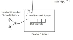
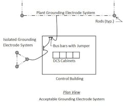
So, with a common grounding electrode system for all electrical equipment and instrumentation, how is a technician supposed to rule out noise on the grounding electrode system if he’s having issues with instrumentation? One acceptable, prevalent method in the petrochemical industry is to provide two grounding bars or buses in the RIE or control building. One bar is used for the plant grounding electrode system, and the other is used for the “isolated” grounding electrode system. Some manufacturers refer to the isolated grounding electrode system as the “master reference” grounding system. Then, inside the building or enclosure, a permanently installed bonding jumper is installed between the two systems to create one electrode system. Using this method allows the instrument technician to troubleshoot should he think that he’s getting noise on the grounding electrode system. This method also achieves the intent of the requirements set forth in Sec. 250.50.
The fallacy here is creating a truly “isolated” grounding electrode system is virtually impossible. It’s extremely difficult to create “isolated” grounding electrode systems. The two systems will inevitably be in contact somewhere — whether intentional or not. And, even if the isolated grounding electrode system is achieved, you’re creating a low-impedance “sink” that actually attracts noise.
Remember that common mode noise or other noise issues are not the “objectionable currents” referred to in Sec. 250.6 of the NEC and never warrants an attempt to create an isolated grounding electrode system. “Objectionable current” as used in this section could be circulating currents for instance. All grounding electrodes must be intentionally connected together at each building or structure served. No switches, spark gaps, or electronic diode devices can be installed between the multiple grounding electrodes.
For more information on sensitive electronic grounding, see IEEE Emerald Book, Std. 1100.
© 2015 Fluor Corporation. All Rights Reserved.


