In general, the wiring methods presented throughout the Code are applicable for photovoltaic (PV) systems. More specifically, Part IV of Art. 690 is titled “Wiring Methods,” which helps us establish the fundamental requirements for conductor selection and installation for PV systems.
Conductor types
One of the most significant allowances for PV systems is the ability to use exposed single-conductor cables for the circuits within the PV array as called out in 690.31(A). USE-2 and PV wire (a relatively new, double-jacketed single conductor cable) are specifically called out as acceptable conductors. Nearly all PV modules available today are shipped from the manufacturer with two single conductors pre-installed to the module’s junction box. The cables also have quick-connect plugs installed to facilitate easier field wiring associated with PV modules.
The home run cables from the modules to the external junction or combiner box for the entire array will use the USE-2 or PV wire called out in 690.31(A). These conductors are usually 12 AWG or 10 AWG, have a matching quick connect to mate to the module wiring on one end, and are terminated on a terminal block or overcurrent protection device at the array junction box or inverter location. At first glance, it may appear these conductors must be color-coded to identify the grounded current-carrying conductor. For these specific conductors, the Code allows the identification to happen at all terminations via use of distinctive marking [200.6(A)(6).] Thus, it’s common to see only black conductors within the array and the terminations marked to indicate polarity. Although color-coded conductors are available, in terms of longevity of insulation, black conductors are considered to have the highest UV resistance and expected lifespan.
Wire management
While not directly covered in Part IV of Art. 690, one area of the installation that can prove very difficult is properly managing the conductors associated with the modules and home run. The pre-installed conductors are great because they make fast field connections; however, they need additional attention during the installation. PV installations should be done with the intention that they will operate for more than the 25-year power warranty that associates most modules with very little maintenance. Considering the harsh locations for most PV modules and associated wiring, the management of these conductors should be a part of all installers’ plan from the beginning.
The array location will have a lot to do with the wire management selected for that array. PV modules mounted on residential rooftops can be some of the most difficult when it comes to wire management. Often, these arrays are mounted with only a few inches between the back of the module frames and the roof surface. To complicate matters, there are often multiple rows of modules with the conductors running in between. As an installer, your No. 1. goal is to keep the conductors secure and free from potential damage. If the conductors aren’t secured and held in place, they can abrade against the roof surface, leading to potential faults. In areas of high snow and ice events, loose wiring can get pulled, damaging connection points and module junction boxes. Another problem is damage caused by animals chewing on the insulation of the conductors.
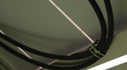
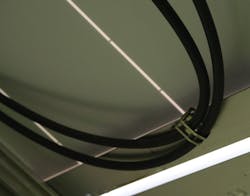
To help aide the installation community, a number of manufacturers offer different wire management products. One popular line promotes wire clips, typically made of stainless steel, which hold the conductors snug to the module frames (Photo 1). The S-shaped clips typically have a barbed slot that slides onto the module frame and bites into the frame for a secure connection. The other portion of the clip has a grooved slot to hold the conductor(s) in place. These clips are available for different wire types and gauges, so make sure you know what wire size you will be working with before ordering them.
Other common solutions include UV-resistant zip ties and the optional accessories that are available for use in conjunction with zip ties. There are products specifically designed to clamp to the edge of module frames that incorporate a zip tie or other clamping mechanism to hold the conductors in place. Some installers question the longevity of such solutions; they feel that even the UV-resistant zip ties will not outlast the system’s expected lifespan. Ultimately, as the installer, you need to make the judgment call on all materials used in your installation.
For systems that are mounted in areas considered to be readily accessible, 690.31(A) has an exception that requires such conductors to be installed in a raceway when the maximum system voltages are greater than 30V. This will be the case for nearly all PV installations, even those using micro-inverters — as most modules have rated open circuit voltages greater than 30V — before temperature corrections.
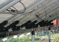
The most common scenario for this raceway requirement is ground-mounted PV arrays (Photo 2). Given the fact that most modules do not have provisions for attaching raceways to their integrated junction boxes, this is not always a simple task. This situation leaves the installer two choices: make the wiring not readily accessible, or find an ingenious way to incorporate a raceway to protect the conductors. Most AHJs will accept a height of 8 feet from grade as an acceptable method for making the conductors not readily accessible, but that generally isn’t an option for ground-mounted arrays. The more common method is to include some sort of barrier, such as a fence, to restrict access to the wiring. Fencing can take the traditional form, enclosing the array or some material connected directly to the racking structure to remove access to the conductors.
Installers have also successfully used wireways, gutters, and modified conduit assemblies to satisfy the AHJ in relation to this requirement. My suggestion is to think through a method that will be effective for your particular installation and make that proposal to the AHJ beforehand.
DC conductors in a building
Section 690.31(E), “Direct-Current Photovoltaic Source and Output Circuits Inside a Building,” was revised in the 2011 NEC. The 2008 language associated with this section was confusing and, in many cases, led to interpretations that included AC circuits. In 2011, the main language of this section was clarified, and four subsections were added to help further define the requirements associated with the DC conductors running in buildings.
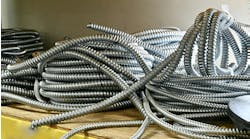
The general rule states that the DC source and output circuits from a PV array shall be contained in metal raceways, MC cable that complies with 250.118(D), or metal enclosures from the first point of penetration to the first readily accessible disconnecting means. One of the clarifications addresses that this requirement is intended for the DC circuits only — not any AC circuits associated with the inverter’s output. The inclusion of MC cable was new to 2011, so be sure to make sure your AHJ is accepting that change if you plan to use this wiring method.
To help keep the circuits safe after the installation and for future maintenance, 690.31(E) now includes subsections restricting conductor location and requiring additional labeling. The first requirement is that when PV circuits are run below roof surfaces — outside of the array perimeter — they shall be no less than 10 inches from the roof decking. This means that if you have a horizontal pipe run that is not directly below the PV array, the pipe must be at least 10 inches below the roof decking. The intention here is to protect firefighters who may need to cut a hole in the roof for ventilation during a fire.
The labels and markings in this section are new as well. They are in place to help ensure the PV circuits are able to be properly identified and no one tries to tap into these conductors at a later date. 690.31(E)(3) describes what components need to be marked and labeled, such as exposed raceways and junction box covers. These require a permanent label that reads, “Photovoltaic Power Source.” These labels must be appropriate for the particular installation environment, requiring proper UV resistance and special adhesives in some cases. These generic labels are available from label manufacturers or can be printed using specific label makers.
The labels must be visible after installation and need to be placed on every section of the wiring system that is separated by walls or partitions — and be spaced no more than every 10 feet. This requirement applies to any exposed wiring method, including wiring methods on a rooftop, attic spaces, and exterior runs.
Ungrounded systems
One type of system that is quickly gaining popularity is one that uses an ungrounded, or transformerless, inverter. These inverters offer a number of advantages over their transformer-based counterparts. However, to install them properly, there are additional Code requirements you must take into account. In terms of wiring methods, 690.35 covers the specific requirements that need to be followed, some of which are very different than the transformer-based installations.
One such difference is the disconnecting means and overcurrent protection. In a transformerless inverter, neither the positive nor negative conductor has a bond to ground. The result is that you no longer have a grounded current-carrying conductor. This requires both conductors in each circuit to be protected with OCPDs and have disconnecting means as required in Art. 690, Part III. This difference can result in larger combiner boxes and disconnects specially designed for ungrounded systems. Even though the current-carrying conductors do not have a bond to ground, there is still a ground fault protection circuit as part of the inverter. This requirement, which is outlined in 690.35(C), is very similar to that set in 690.5.
The conductors used in the PV source circuits are also subject to requirements different than the transformer-based inverters. In 690.31(A), two types of conductors were called out as appropriate, but in ungrounded systems, only PV wire is allowed for exposed, outdoor locations. Other options include conductors installed in raceways and nonmetallic jacketed multiconductor cables, but neither of these are effective options, given the construction of PV modules today. If installing an ungrounded inverter, the PV modules used must come with the PV wire attached to them, not USE-2. Although most manufacturers have already made this change, it is not universal at this point.
The differences in installation requirements wouldn’t be complete without some additional labeling requirements. For PV systems using ungrounded electronics, all locations where conductors may be exposed during service need to have a label warning of the ungrounded conductors. 690.35(F) includes the specific language required for such components.
As you can see form this brief review, there are a number of considerations and requirements focused solely on the wiring methods for PV systems, specifically on the DC side of the system. Putting that little extra effort into wire management procedures during the installation process will pay off in the long term, helping to ensure your system operates safely and efficiently for many years.
Mayfield is a principal with Renewable Energy Associates, Corvallis, Ore. He can be reached at [email protected].
