All questions and answers are based on the 2005 NEC.
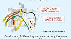
Q. Can 277V circuit conductors be placed within the same raceway with 120V circuit conductors?
A. Yes, power conductors of different systems can occupy the same raceway, cable, or enclosure if all conductors have an insulation voltage rating not less than the maximum circuit voltage [300.3(C)(1)] (Figure).
Q. Is all electrical equipment required to be listed?
A. Not all electrical items required or permitted by the NEC are required to be listed; however, if the equipment you are using is listed, it must be installed and used in accordance with any instructions included in the listing or labeling requirements [110.3(B)].
There are many products that the NEC does require to be listed such as receptacles [406.2(A)], low-voltage lighting systems [411.3], EMT fittings [358.6], grounding and bonding fittings [250.8] and many others. Because of this, it may be worth your time to use all listed products, since the NEC requires so many items to be listed. Also, there are some states, such as Washington and Minnesota, that require all items be listed — so be sure to check any local amendments in your jurisdiction.
Q. I've been told that when conductor ampacity adjustment is required (bundling or ambient temperature), we are to determine the conductor ampacity based on the temperature rating of the terminals in accordance with Table 310.16. Is this true?
A. No, conductor ampacity adjustment is based on ampacity of the conductors in accordance with the temperature rating of the conductors. Typically conductors used today are THHN in a dry location. For these circuits, the ampacity is based on the 90°C rating of Table 310.16. [110.14(C)(1)(a)(2) and 110.14(C)(2)(b)(2)].
For example, if we bundle three 12/2 and one 12/3 cables (nine current-carrying 12 THHN conductors), the ampacity for each conductor (30A at 90°C, Table 310.16) is adjusted by a 70% adjustment factor [Table 310.15(B)(2)(a)]. And the adjusted ampacity value is calculated as follows: adjusted conductor ampacity = 30A × 0.70 = 21A.
Q. How do I size the ground wire for a circuit when the hot wires have been increased in size because of voltage drop?
A. When ungrounded circuit conductors (hot wires) are increased in size for any reason, the equipment grounding (bonding) conductor must be proportionately increased in size [250.122(B)]. For example, if the ungrounded conductors for a 40A circuit are increased in size from 8 AWG to 6 AWG, the equipment grounding (bonding) conductor must be increased in size from 10 AWG to 8 AWG. This is because the circular mil area of 6 AWG is 59% greater than 8 AWG (26,240 cmil ÷ 16,510 cmil) [Chapter 9, Table 8]. According to Table 250.122, a 40A circuit protection device would require a 10 AWG equipment grounding (bonding) conductor, but it must also be increased in size by 59% (10,380 cmil × 1.59) = 16,504 cmil), which results in a 8 AWG.
Q. What precautions must I take when splicing aluminum conductors to copper?
A. Copper and aluminum conductors must not make contact with each other in a device unless the device is listed and identified for this purpose [110.14]. Few terminations are listed for the mixing of aluminum wire and copper, but if they are, they will be marked on the product package or terminal device.
The reason copper and aluminum should not be placed in contact with each other is because corrosion develops between the two different metals due to galvanic action, resulting in increased contact resistance at the splicing device. This increased resistance can cause overheating of the splice and result in a fire.


