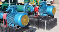
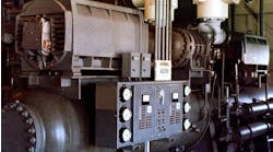
Art. 430, Part III provides the requirements for motor and branch-circuit overload protection. Because of inrush current, overload protection is separate from overcurrent and ground fault protection when you’re dealing with motor circuits.
Motor overload devices protect motors, motor-control apparatus, and motor branch-circuit conductors from excessive heating due to motor overloads and failure to start [430.31]. An example of a motor overload situation is a motor-driven mixer with too thick of a slurry in the vat, and the motor works harder than intended to turn the impeller. This isn’t enough to trip the breaker, but it is enough for the motor to get too hot.
Short-cycling motor starts is another form of overloading the motor. Each start generates heat in the motor; if there is not enough time between starting attempts for that heat to dissipate adequately, the motor overheats.
This concept of accumulated heat due to starting leads to a natural division of requirements for continuous-duty motors [430.32] and intermittent-duty (and similar) motors [430.33].
The way in which these requirements differ is the latter type — as illustrated by Table 430.22(E) Duty Cycle Service — can be protected against overload by the breaker (branch-circuit short-circuit and ground-fault protective device) if the device rating or setting does not exceed what’s specified in Table 430.52 [430.33].
This seems like a way to simplify your motor installation, except the following language in 430.33 can quickly nix the idea: “Any motor application shall be considered to be for continuous duty unless the nature of the application is such that the motor cannot operate continuously with load under any condition of use.”
If a motor is continuous-duty (per the language in 430.33) and rated over 1 HP, you must choose and use one of three options for providing overload protection [430.32(A)]:
- Separate overload device. For example, heater strips mounted in the motor controller enclosure.
- Thermal protector integrated with the motor. For example, a thermal relay mounted in the motor enclosure near the windings.
- Protective device integrated with the motor that opens upon failure to start. An example is a one-shot switch requiring the operator to reset it using a reset button. The motor must be part of an approved assembly that does not normally subject the motor to overloads.
What if you selected or set the motor overload device per 430.32(A)(1) and (B)(1), but it won’t let the motor start or carry the load? In that case, you can use a higher-size sensing element or incremental setting, but only if the trip current doesn’t exceed X percentage of the motor nameplate full-load current rating [430.32(C)]. What is X? It’s 140% for motors with a marked service factor of at least 1.15 or with a marked temperature rise of 40° C (104° F) or less. It’s 130% for all other motors.
Before you start down the path of increasing the motor overload device size or setting, stop to examine the motor system. During preoperational testing in an Illinois electrical generating station, a large pump motor in the feedwater system would not start. The young systems engineer was flummoxed. While he was going over his drawings and scratching his head, an instrument tech arrived to help him figure out the problem.
The tech was there less than a minute when he pointed to a large valve just downstream of the pump. It was closed, thus deadheading the pump. The motor was essentially trying to provide enough torque to compress water, and water is (for all practical purposes) incompressible. Once the valve was fully opened, an attempt to start the motor was made; it succeeded.


