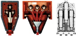
When it comes to terminating motor leads, there are many schools of thought — each of which has a following that thinks its camp has the best method. This article does not consider motor starting methods or internal connections. Instead, it describes some procedures for connecting motor leads to incoming power and a few advantages and disadvantages of each. It also explains how to insulate joints and splices without using epoxy or tape kits.
Types of terminations. Acceptable methods of connection include both mechanical and crimp compression lugs. Connections that use twist-on connectors are only acceptable for wire sizes no larger than 10 AWG. [See the National Electrical Code, 2017 (NFPA 70-2017), Sec.110.14A.]
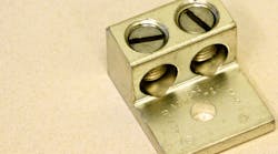
Mechanical compression lugs. These connectors secure the conductors with set screws and are available in configurations having one to six or more barrels (Photo 1). The lugs are installed on both the motor leads and the power supply leads and then bolted together. Parallel motor leads and power supply conductors should use lugs that have the same number of barrels as there are leads.
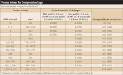
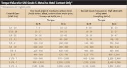
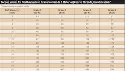
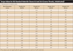
Tighten the set screws to secure the wire using the NEC recommended torque values (Table 1). The bolt holding the lugs together should also be torqued to the correct value (Tables 2, 3, and 4). If the lug and bolt are made of different materials, they may expand and contract at different rates. In that case, use a Belleville washer to maintain torque and help keep the bolt from stretching.
Note: The torque values in Tables 2, 3, and 4 are approximate and should only be used in the absence of manufacturer’s specific tightening values. Indeterminate factors such as surface finish, plating and lubrication preclude the publication of accurate values for universal use.
Oxidation will increase the resistance and heating in the termination, so it’s a good practice to coat the conductors and mating surfaces of lugs with an anti-oxidant formulated for this purpose. The same applies to all other connections discussed in this article.
Advantages and disadvantages. Mechanical compression lugs are easy to use and require no special tools — typically, only a torque wrench with a hex head (Allen) or slotted head socket are required. These connections also can be used where the motor is terminated on a bus bar in the terminal box. One disadvantage is that the secureness of the connection relies on the tightness of the set screws and the bolts that hold the lugs together.
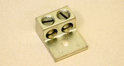
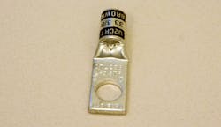
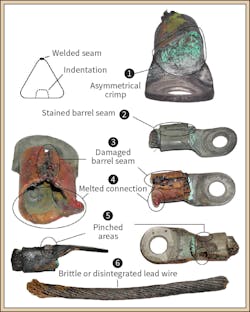
Crimp compression lugs. These lugs (Photo 2) attach to the conductors using specially designed mechanical or hydraulic crimping tools. Since the lugs come in various sizes and profiles (e.g., indented, hexagonal, or lobed), it’s critical to use the right crimping tool to avoid loose connections, damaged conductor strands, or misshapen crimps (Fig. 1).
Some crimp compression lugs are formed from a sheet of conductor material, so the barrels have a seam. To prevent split seams and loose joints, position the crimping tool so that it will indent the opposite side of the lug.
Crimped lugs bolt together in the same way as set screw lugs (which was discussed earlier); but, for obvious reasons, they don’t have multiple barrels. Therefore, each parallel conductor requires a lug, and a bolt holds all the lugs together.
Advantages and disadvantages. The crimp connection will securely join the conductor and lug if the proper tool is used. It also can be used where the motor is terminated on a bus bar in the terminal box.
One disadvantage of crimped connections is that each different lug profile and size requires a special tool. One way to minimize this problem is to standardize on the products of one lug manufacturer. That way, only one set of crimping tools may be needed. Smaller tools often accommodate three or more wire sizes. Larger hydraulic tool sets can have multiple dies for different lugs.
Insulating joints. Motors with voltages up to 2kV. Splice insulation kits with explicit instructions are readily available to make well protected joints for motors operating at less than 2kV. Some use epoxy resins; others use various tapes. Both have the same objective — to electrically insulate the joint from its surroundings while mechanically protecting it from damage due to vibration, heat or impact.
To insulate a joint without a kit (Photo 3), proceed as follows:
• Obtain adequate supplies of varnished cambric, rubber or rubber mastic, and vinyl tapes.
• Ensure the connection is free of dirt, oil, moisture, or other contamination.
• Wrap the joint with two half-lapped layers of varnished cambric tape to prevent any sharp edges from piercing subsequent tape layers. A half-lapped layer is one where the second lap of tape around the joint covers one-half of the lap below it. When finished, there will be two thicknesses of tape per side in each half-lapped layer. If the varnished cambric has adhesive, face that outward.
• Next, wrap with four half-lapped layers of rubber tape. Rubber tape doesn’t usually have an adhesive, but it will bond to itself if wrapped with constant tension.
• Finish with at least two half-lapped layers of vinyl electrical tape. This will hold the rest of the tape together, while adding electrical and mechanical protection. Extend the tape a couple of inches (about 51 mm) along the wires to help seal out contaminants and reduce the possibility of shorting.
Motors with voltages above 2kV. These motors require shielded cable. This will distribute the voltage stress along the length of the cable and prevent localized partial discharge at points where the cable is adjacent to metal structures.
• To be effective, the shielding should be continuous from the power supply to the motor termination.
• To avoid voltage buildup, ground the shield at each point where the conductor terminates, including splices. This will cause a circulating current in the shield that produces heat. If the current in the shield circuit exceeds 5% of the current in the conductor, reduce the current carrying capacity of the conductor. Multiple variables determine the heating effect, so consult the wire vendor for the appropriate derating factors.
Medium voltage stress cones. Proper termination of the shielded cable includes stress cones to help the transition from insulated conductor to conductor in air (Fig. 2 and Fig. 3). Partial discharge can occur at any transition point — e.g., where a lead emerges from a stator core, a pointed section of winding like a stub connection in a form coil or, as discussed here, a break in the insulation and shielding system. In the case of the latter, a stress cone mitigates its effect.
Conclusion. Although there are many ways to terminate motor leads, it’s important to use recommended methods like mechanical or crimp compression lugs to prevent failures. Connections and joints must also be insulated properly, using readily available epoxy or tape kits or the application of protective and insulating tapes (as outlined above).
Bryan recently retired from EASA, St. Louis, Mo., where he was a technical support specialist. Contact EASA at [email protected].
