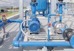
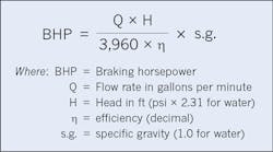
An important step when selecting a centrifugal pump and an electric motor for an application or when troubleshooting operation issues is to determine how much power the pump should be using. The “by-the-book” approach references the pump curve, which shows the power requirement for the pump’s range of operation (head and flow rate). While that’s the best approach, a simple, universal formula based on the relationship of power, head, flow rate, and efficiency can provide realistic estimates for general planning or primary troubleshooting (Fig. 1).
Because the head and flow rate are determined by the pump application, these requirements are calculated during the system engineering stage for new or proposed installations. Ideally, this data is then stored with the asset management system. The head and flow rate data will cover a range of operating conditions, so to accurately assess the power required when troubleshooting existing installations, those values should be measured at the pump site.
A good approximation of the head is simply the discharge head minus the suction head, as measured at the pump with basic pressure gauges. For water, gauge pressure multiplied by 2.31 equals head in feet. Measuring flow rate can be more difficult if the system doesn’t have such instrumentation. In those cases, the most direct method is to use portable instruments with sensors mounted to the pipe surface.
For structured sump systems like sewage lift stations, a reasonable estimate of flow rates can be made by monitoring the sump level. With any flows into the sump temporarily closed off, the drop in sump level for a period of time (minutes) indicates the flow rate. A simple calculation will convert sump level to cubic feet or liters, thus yielding the flow rate in cubic feet per minute or liters per minute. Once the head, flow rate, and specific gravity are known, the required power can be calculated with the formula in Fig. 1.
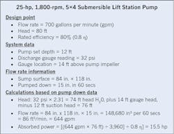
Figure 2 illustrates a real-world example of a lift station pump. In this case, a power meter measured the actual 3-phase power to be 12.6kW, or 16.8 hp (458V, 21A, 0.82 PF, motor efficiency rated 92%). Therefore, the pump is using more power than it should to produce head and flow rates that are below the design point (80 ft and 700 gpm).
Some might question the accuracy of the sump pump down measurement. But allowing even an inch of error and recalculating at 16 in. of pump down results in 686.5 gpm flow rate (still significantly below the design point) and absorbed power of 16.5 hp:
Absorbed power = 686.5 gpm × [(76 ft ÷ 3,960) ÷ 0.8 h] = 16.5 hp
Based on these calculations, this system was clearly under-performing. When inspection of the pump revealed only slight cavitation damage at the impeller suction eye, troubleshooting proceeded to the sump, where a buildup of sludge was found at the pump suction location. This restriction caused cavitation, reducing the flow rate and the efficiency of the pump.
As this example shows, the power formula for centrifugal pumps makes it possible to identify operational problems without referencing the pump curve. It can also be used to estimate the power requirements for new pump installations or for changing conditions for existing pump applications.
Vogel is a pump and vibration specialist at the Electrical Apparatus Service Association, Inc. (EASA) in St. Louis. He can be reached at [email protected].

