Instantaneous vs. Inverse Time Circuit Breakers for Motors
Article 430 in the National Electrical Code (NEC) recognizes two types of molded case circuit breakers (MCCBs) — instantaneous and inverse time — for motor branch circuit short circuit and ground fault protection, in addition to fuses. There’s an important difference between these two types of circuit breakers.
Instantaneous trip breakers do exactly what the name implies. When the current in the circuit reaches a value that the breaker trip mechanism is set to, it will trip off instantaneously with no time delay. Instantaneous breakers are magnetic trip only. Instantaneous breakers are also referred to as motor circuit protector breakers or MCPs.
Inverse time breakers, on the other hand, have a time delay mechanism that will allow the breaker to delay tripping off. The amount of time delay decreases as the current increases. Inverse time breakers are thermal-magnetic. Many in the industry use the slang term “thermal-mag” breakers for inverse time breakers.
More often than not, in industrial locations, MCPs are used in combination starters for motors. The MCP breaker is used for the motor branch circuit short circuit and ground fault protection in conjunction with a motor starter with overload protection (heaters or electronic overloads). MCPs typically have a dial(s) on the front of the breaker that allows the user to define what the trip current is. When using MCPs for motor circuit protection, it’s important to consult the breaker manufacturer’s data to see where to set the trip threshold as the NEC has limits for the setting. Not all breakers have this information on the breaker itself, or the information may be covered up with an operator lever such as found in a motor control center.
Instantaneous trip breakers may only be used as part of a listed combination motor starter unit. MCPs will not protect the motor from overload or overcurrent. This is the reason that MCPs can only be used as part of a listed combination starter unit. The overload unit will protect the circuit conductors and the motor from overcurrent and overload, respectively. It should also be noted that the use of an MCP for a valve actuator motor (VAM) assembly is usually prohibited since the controller for most VAMs are within the valve actuator unit.
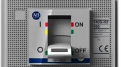
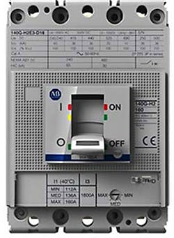
Sizing an MCP is relatively simple. For example, let’s assume we have a squirrel cage, 25-hp, 480V, 3-phase, Design B, energy-efficient motor. Using the values in Table 430.250, we find that the full-load continuous current to be used in our calculation for the breaker is 34A. In Table 430.52, the initial maximum setting is 1,100% of 34A, or 34A x 11 = 374A. The reason for the 1,100% multiplier is to allow the motor locked rotor current to occur without tripping the breaker. The MCP chosen may have a continuous ampere rating of 50A in this case, and the settings on the dials on the front of the breaker may be set anywhere from a minimum of 30A to a maximum of say 500A, for example. Care must be taken not to set the dials any higher than the NEC allows, which in this example is 374A. The dial(s) may not have ampere ratings on them, (see Photo). Many times, there are alpha characters, numerals, or min/mid/max indicated for the settings, and these characters correspond to a defined ampere rating.
Indiscriminately cranking the dial(s) wide open to the maximum could — and probably will — create a Code violation. Many times, electricians don’t have the dial setting data available to them when commissioning the installation and may end up “winging it” (guessing at) the settings so that the motor will start and not trip the breaker — having no idea what value the breaker is set to trip at. Always use vendor data to set the breaker trip value in accordance with the values allowed by the NEC.
As far as the maximum current settings on the breaker, Sec. 430.52 of the NEC has an Exception that allows a setting higher than 1,100% under certain conditions. The design engineer as well as the electrician should be very familiar with all NEC requirements and the equipment involved to ensure a safe and Code-compliant installation.
© 2015 Fluor Corporation. All Rights Reserved.
