When you get the call, “The motor won’t start,” you’d best have a logical and systematic plan in place to approach the problem. “Easter egging” just doesn’t work unless you happen to be very lucky!
“Maybe it’s the limit switch again” or “Probably another ground fault on the motor” is not the way to minimize troubleshooting time and increase uptime on equipment. The key to developing a logical and systematic approach to troubleshooting motors and controls is to first understand the overall concept of the motor and its associated control circuit — and then use the skills and techniques necessary to read through the control circuit diagrams and compare expectations to what is actually happening at the components. For example, if you interpret the control circuit as telling you contacts “CR105-3” should be closed, then you need to have the skills to find the CR105 relay and measure voltage across the number “3” set of contacts and determine if they are open or closed.
Typical motor circuits are divided into two main parts: the main power circuit and the control circuit. This article will help you understand how to trace voltage through the main power supply circuit. This can help to isolate the problem to the power supply, the control circuit, or the motor itself. In Part 2, we’ll address reading basic to more complex control circuit diagrams and show you how to develop a logical and systematic approach to troubleshooting control circuits.
When beginning the investigation, look for the obvious. Any signs of motor overheating, such as the smell of burnt insulation, might indicate a motor ground fault and internal damage. Mechanical issues such as broken couplings can be quickly spotted. Overload trips are a common problem. If the distinctive “click” is felt as the motor starter overload reset push button is depressed, then the cause of the overload must be determined. Knowing your system and control circuit is critical to ensure the motor will not automatically restart when resetting overloads.
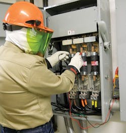
If there are no obvious indications as to why the motor does not operate, it’s time to use your multimeter and look for the “missing voltage” in the main power circuit. Begin troubleshooting by simply following the electrical flow path from left to right as the current flows toward the motor. The objective is to find where the voltage is interrupted to the motor. It is always safest to first place a motor and control circuit into an electrically safe work condition through proper lockout/tagout procedures and then test for continuity. However, diagnostic troubleshooting must often take place with circuits energized. When working on energized circuits, always follow OSHA and company electrical safe work practices (Photo).
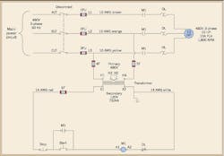
The missing voltage concept means finding the point where voltage should be present, but for some reason it is not. Refer to Fig. 1, and use this concept to walk through a basic motor control circuit. Remember, when testing for the presence of 3-phase voltage, always read across all phases: A-B, A-C, and B-C. Make sure all readings are within specification.
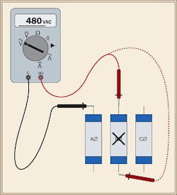
First, test for voltage at the top of the disconnect. If voltage is present, move to the right on the electrical diagram and test for voltage at the top of the fuses. One of the most common problems is open (blown) fuses. If voltage is present at the top of the each fuse, use a crisscross method to verify the fuses are good (Fig. 2).
The next points along the flow path to the motor — the “M1” contacts — are tested at the top of the motor starter. Once again, test across all three phases. If voltage is present, then test for voltage at the bottom of the starter. If voltage is not present at the bottom of the motor starter, test the points where voltage is applied to the coil. These are points A1 and A2 in Fig. 1. If voltage is not being applied to the coil, then the problem is in the control circuit.
If the coil is energized, but voltage is still not present at the bottom of the motor starter and the motor is not operating, a dangerous condition could exist. The problem is possibly open overload thermal elements, wiring to the motor, or — most likely — the motor itself. Shutoff the power, lock/tagout as required and begin investigating such issues.
The main power circuit can be relatively easy to troubleshoot, but there are no guarantees. Each situation is different and requires the ability to read and interpret the circuit diagrams. Once circuit operation is understood, follow a logical, systematic plan to isolate the cause as to why the motor did not start. Always de-energize if possible, and follow safe work practices. Keep in mind that the most common problems in the main power circuits include a loss of upstream power, open fuses, main line contacts (M1) not closing because of control voltage not being applied to the starter coil, and tripped overloads. Part 2 will address reading, interpreting, and troubleshooting the control portion of the circuits — from basic concepts to more complex circuits.
Barnett is electrical codes and safety program manager for NTT, Centennial, Colo. He can be reached at [email protected].


