In Part 1 of this two-part series, we presented a 3-phase, 480VAC motor circuit with its associated controls (Figure). We stepped through a logical, systematic approach to troubleshoot the main power portion of the circuit from the incoming power location through the fused disconnect, starting contacts, and overloads to the motor. If all of the above items checked out satisfactorily, yet the motor didn’t start, the next most likely section of the system to troubleshoot is the control circuit. We’ll first discuss how to examine the circuit shown in the Figure with a multimeter, and then we’ll present and examine a practical, more complex and realistic control circuit you’ll find in the field.
Basic operational notes
To begin troubleshooting, first gather up the most recent prints for the applicable circuits and systems. Also, pull out any notes from your previous work on these circuits and a standard set of control device symbols or a list of the specific symbols being used in the drawings. To develop a logical and systematic approach to troubleshooting, spend some time with the prints and colored markers learning how the circuit operates, take notes, and highlight on the prints as needed. Without these tips, troubleshooting can quickly become a no-win guessing game.
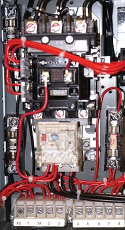
shows a typical motor controller. The contacts that start and stop the motor are physically located inside of the starter. They are depicted with M1 symbols in the upper right of the Figure (line reference numbers 101, 102, and 103).
The schematic diagram is shown in its normal state (i.e., before any physical action has taken place on the circuit). Once the disconnect in the main power circuit closes, the START pushbutton is depressed, which applies voltage to the M1 coil. As current flows through the coil and returns back to the X2 side of the transformer, a magnetic field is created around the starter coil. This field attracts a ferrous plunger that is attached to the contacts. As the plunger is pulled in by the magnetic field, the contacts in the starter are closed. Note the numbers at the right side of reference line 108 (near the black probe). These numbers indicate where these contacts are electrically located in the circuit. The associated contacts on those lines are labeled “M1,” which reflects the coil that operates them. Closing the 480V main line contacts applies voltage to the motor. The contact on line 107 is the “holding” or “maintaining” contact. This contact closes immediately when the M1 starter coil is energized. Note that this holding contact is in parallel with the START pushbutton. This allows the START pushbutton to be released, and power remains applied to the starter coil. The operator can walk away from the control panel, and the motor continues to run.
De-energizing the motor can be accomplished by depressing the STOP pushbutton, which, in turn, de-energizes the M1 starter coil. This causes its magnetic field to collapse, which allows spring pressure to pull the ferrous operating bar back to its normally de-energized state. This will open contacts in the 480V circuit and de-energize the motor. Also, since the M1 holding contact returns to its OPEN state, the START pushbutton will have to be depressed once again to start the motor; it will not restart automatically. It’s also important to note the overload heaters (OL) [shown in the upper right of the Figure (line reference numbers 101, 102, and 103)] can cause the O.L. contacts (line reference number 108) to open and de-energize the M1 coil.
Terminology is important in troubleshooting. Since the contacts shown on reference lines 101, 102, 103, and 107 are open while the M1 coil is de-energized, the contacts are said to be “normally open.” Since energizing the M1 coil will close these contacts, the troubleshooting terminology often used here is, “the normally open contacts have closed.” Note that even though these contacts are closed while the coil is energized, they are still the normally open contacts. De-energizing the M1 coil will cause these contacts to return to their normal state (i.e., OPEN). Note that the overload (O.L.) contacts on reference line 108 are closed as depicted by their symbol. Therefore, the O.L. contacts are “normally closed.” The overload heater elements can cause these normally closed contacts to open. As contacts open and close, they “change state.” The STOP pushbutton contacts on reference line 108 are normally closed; the START pushbutton contacts are normally open. Depressing either pushbutton will cause its associated contacts to change state.
The test sequence
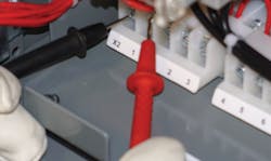
The multimeter shown in the Figure helps depict the troubleshooting steps used to isolate problems in the control circuit. One multimeter test lead (typically the black for consistency) is placed at a convenient point on the grounded (i.e., X2) side of the control circuit. The opposite test lead (red) is used to “walk through” the circuit.
Follow these steps to begin tracing voltage through the circuit:
1) Place the red test lead at point 1 (Terminal 1 of the terminal strip of Photo 2) in the circuit, where power enters the STOP pushbutton. In Photo 2 this corresponds to test leads placed on the “X2” and “1” terminals located beneath the starter. If voltage isn’t present at this point, the fuse is likely open. If the meter indicates voltage is present, continue to the next step.
2) Move the red test lead to point 1A on the schematic (Terminal 1A in Photo 2). If the meter reads zero at this point, then the STOP pushbutton contact is open, and the cause must be investigated and repaired.
3) Move the red test lead to point 3 on the schematic (Terminal 3 in Photo 2). Voltage shouldn’t be present until the START button is depressed. If voltage doesn’t appear at point 3 when START pushbutton is depressed, suspect a faulty start switch.
4) If voltage is present at point 3 and the motor didn’t start, test for voltage at A1 on the starter itself. If voltage is applied to the coil at A1 as expected, and the circuit still doesn’t operate, faulty overloads may be the problem — even though an attempt was made to reset them initially when investigating the main power circuit (see Part 1 of this series).
5) To verify the overload contacts aren’t open, place the red test lead at terminal 95 on the overload relay contacts when depressing the START button. If voltage appears at this terminal, the overload contacts appear to be open as voltage is simply now being read across a set of open contacts. Correct the overload contact problem.
A real life example
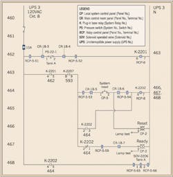
The control circuit shown in the Sidebar (Understanding the Ladder Diagram) is a typical, application found in a process control system. Studying this circuit proves that understanding the sequence of events in circuit operation is the most important step in the troubleshooting process. Once circuit operation is understood, the troubleshooting process can begin, and it simply becomes a matter of following voltage through the circuit. Troubleshooting involves testing for voltage at the correct terminal in the appropriate control panel while reviewing the electrical schematic or ladder diagram. As you test for voltage, ask yourself, “Should I have voltage at this point? And, if not, what component or device in the circuit before this point is open?”
Note that troubleshooting isn’t black and white. Loose terminal screws, broken control wires underneath a terminal screw, and improperly wired circuits during installation or maintenance modifications are all problems occasionally seen in the field.
Barnett is electrical codes and safety program manager for NTT, Centennial, Colo. He can be reached at [email protected].
SIDEBAR: Understanding the Ladder Diagram
One of the first steps to successful troubleshooting is to understand the concept of the ladder diagram. Control circuits may be arranged much like a ladder (i.e., with rails vertically on each side and rungs horizontally between the rails). Just as you step your way down a ladder from the top, troubleshooting requires you step your way down a ladder diagram, one rung at a time, while analyzing each rung from left-to-right.
The circuit in the Figure is a facility process control system that allows an operator to recharge a tank if tank pressure drops below a certain point. To re-pressurize the tank, certain conditions (i.e., permissives) must be met, and the tank must stop pressurizing automatically at a given set point.
Let’s walk through the circuit operation to show you how it works.
• Upon low pressure in the system, PS-22-1 contacts are closed, and the K-2201 relay is energized, thus closing contacts on rung 463.
• Rung 463 contact K-2207 is closed when the K-2207 coil is energized. (Coil is on a later rung and not shown). Certain conditions must be met to operate these contacts, and line 593 would have to be analyzed to determine specifics.
• On Rung 463 with both the K-2201 and K-2207 contacts closed, the YELLOW READY lamp comes on, indicating the system is ready to be re-pressurized.
• On Rung 464 depressing SYSTEM RESET energizes K-2202. GREEN RESET lamp will be ON as soon as the RESET button is pushed.
• Rung 466 contact closes and is a holding contact for SYSTEM RESET.
• Rung 467 K-2202 contacts open to turn off the YELLOW lamp.
• The contact on line 468 closes to energize the solenoid-operated valve SOV-2206, which begins re-pressurizing Tank A.
• When the tank pressure returns to normal, PS-22-1 opens at its high-pressure set point to de-energize all relays and lamps, and de-energize SOV-2206 to stop pressurizing the tank.
