A new edition of the only American national standard for repair of motors and generators — “ANSI/EASA AR100-2010: Recommended Practice for the Repair of Rotating Electrical Apparatus” (ANSI/EASA AR100-2010) — was published recently by the Electrical Apparatus Service Association (EASA). The best practices it provides for mechanical repair, rewinding, and testing help apparatus rebuilders maintain or enhance the energy efficiency and reliability of both AC and DC motors and generators. This article focuses strictly on the electrical aspects of AC machine repair that ANSI/EASA AR100-2010 prescribes, as well as their importance for end-users.
Compared to the 2006 edition, ANSI/EASA AR100-2010 contains more than three dozen changes. Many of these are best practices for maintaining motor efficiency that were identified during a comprehensive “rewind study” published in 2003 by EASA and the Association of Electrical and Mechanical Trades (AEMT), a United Kingdom service center association.
For end-users, one value of ANSI/EASA AR100-2010 is that in just 22 pages it concisely describes “good repair practices.” It also provides six pages of supplemental information. End-users who require service centers to comply with the recommended practices in AR100 can also be assured that repairs will be made in accordance with a recognized American national standard. The result should be a “good practice repair” — i.e., a quality repair without shortcuts.
General guidelines
“General” guidelines provided by AR100 include making sure the machine has a nameplate and recording the nameplate data. By reviewing this data, the service center can ensure the machine is suited for its application — and that repairs will maintain its original ratings. AR100 also recommends that the service center determine the root cause of failure and actions that can help prevent a recurrence. This requires careful inspection and testing of the machine before repairs are made.
While some of the good practices in AR100 may seem inconsequential, their combined effect establishes the document as the good practice repair standard for motors and generators. It also has efficiency as a strong underlying theme, even though it was not specifically written to maintain or improve motor or generator efficiency.
Rewinding
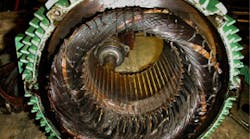
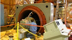
AR100 concisely describes the requirements for a good practice rewind in just two pages, beginning with inspection of the windings (Photo 1) and rotor squirrel cages. It’s easy to forget that the rotor is an electrical component — the rotating secondary of a transformer, with the stator being the primary. This is important, because defective rotor bars or end rings (Photo 2) could reduce output torque or cause vibration.
Winding data. Exact duplication of the original winding is crucial to maintaining motor performance and energy efficiency. Thus, as a preventive measure, AR100 recommends recording and checking the accuracy of the “as-found” winding data before destroying the old winding. In this regard, it also recommends that in the new winding the average length of the coil extensions should not increase — and that the cross-sectional area of the conductors should be the same (or increased, if possible). Following these good practices will maintain or reduce winding resistance and losses, thereby maintaining or increasing winding life and energy efficiency.
Stator core testing. Stator cores consist of a stack of thin steel discs called laminations, each of which is insulated on all surfaces and has a circular opening for the stator bore. Notches around the circumference of the opening form slots to hold the winding. If shorts develop between the laminations, circulating currents will increase stator heating and losses.
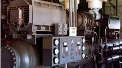
AR100 provides good practices for core inspection and testing, with a focus on detecting core degradation, such as shorted laminations. For example, it prescribes loop or core testing (Photo 3) before and after winding removal, investigation of any increase in core losses, and repair or replacement of damaged laminations. This helps identify a faulty core before (not after) repair — or worse, after the customer places the repaired machine in service.
Winding removal. How to remove (strip) the old windings from the stator core without damaging the laminations receives special attention in AR100. One specific practice it provides is to first thermally degrade the winding insulation in a temperature-controlled oven, while monitoring the temperature of the part (typically the stator), helping to prevent damage to the stator core when the windings are removed.
Insulation system. AR100 also recommends ensuring that the insulation system of the new winding is equal to or better than the original — and that all components are compatible. The “better than” option is normally achievable, because service centers typically use Class H systems (180°C) for random windings and Class F systems (155°C) for form coil windings. Most original manufacturers use either Class F (155°C) or class B (130°C) random windings and class B (130°C) form coil windings.
Rewind procedure and slot fill. Regarding the rewind process, AR100 says the new winding should have the same electrical characteristics as the original. This is best accomplished by “copy rewinding” — for example, using the same size conductors (wire cross-sectional area), the same number of turns per coil, and the same coil dimensions as the original.
Another way AR100-2010 can help end-users improve efficiency in some cases is to increase the wire cross-sectional area, which increases conductivity and reduces losses. They can also reduce the average length of coil turns, which, in turn, reduces resistance and losses.
Guidance on how to repair rotor squirrel cage and amortisseur windings reinforces the need to maintain the machine’s original performance characteristics. This includes making certain that rotor bars fit tightly in the core slots, that bar-to-end ring connections are welded or brazed (Photo 4), and that the rotor cage retains its original electrical characteristics and can withstand normal thermal and mechanical forces.
Winding impregnation. AR100 also stresses good practices for winding impregnation. Key points include preheating the stator winding, using varnish/resin with an adequate thermal rating, and ensuring that the treatment is both compatible with the insulation system and suitable for the application environment. Although every part of the rewind process is important, the cured varnish/resin literally is the “tie that binds” the winding components together. It also ensures good heat transfer from the winding to the stator core and to cooling air.
Testing and Inspection
Following the good practice procedures in AR100 builds quality into the repair. As an example, the document devotes an entire section to inspecting and testing repaired machines — often prescribing multiple tests to verify their suitability to perform in accordance with nameplate ratings. Recommended procedures include careful inspection, followed by winding resistance, surge comparison, and high-potential testing. As explained below, these procedures may detect a fault or anomaly that could cause premature winding failure.
Inspection. AR100 recommends that the windings and insulation system be carefully inspected for damage or degradation before performing insulation resistance, surge comparison, or high-potential tests. The main purpose of this procedure is to detect and correct existing damage that might escalate under test and possibly destroy a new or overhauled winding.
Insulation resistance test. Following inspection, testing begins with the insulation resistance test. This test can detect an incorrect winding if the resistance value of the original manufacturer is known; and it may detect a high-resistance connection (e.g., if one pair of leads has higher resistance than the others).
Often called a “megger test” (a trade name of Megger Group, Ltd.), it measures winding insulation resistance in megohms after a constant test voltage has been applied for 1 minute. This is long enough for insulation dielectric stress conditions to begin to stabilize, which results in repeatable test values.
AR100 recommends testing the insulation resistance of the winding prior to high-potential testing; this could save a winding with weak ground insulation from a test that could cause it to fail. The document includes acceptable test ranges for various machine ratings, as well as recommended minimum insulation resistance values, corrected to 40°C (click here to see Table). If a winding does not meet these minimum values, a high-potential test should not be performed.
Surge comparison tests. Whereas insulation resistance tests apply only to the ground insulation system, surge comparison tests (Photo 5) can detect shorts within the winding (e.g., turn-to-turn, coil-to-coil or phase-to-phase). AR100 provides a suggested test level for surge comparison testing — two times the circuit rating plus 1,000V. This essentially “breaks new ground,” because this criterion is not dealt with specifically in other standards.
High-potential tests. High-potential testing stresses the insulation system of the winding conductors to ground, so AR100 cautions that it should not be done unless acceptable inspection and insulation resistance test results have been obtained.
The standard provides test levels for new, reconditioned, or not reconditioned windings, as well as comprehensive tables illustrating AC and equivalent DC test voltages. (The AC test voltage level is multiplied by 1.7 to obtain the equivalent DC voltage.) Among its advantages, the DC high-potential test requires an instrument with a much smaller capacity than the AC version. Therefore, it does less damage if a failure occurs.
For a new winding, the test level is the maximum value (100%) given in the tables. After machine assembly, the test level is 80% of the maximum. Both the 100% and 80% test levels are limited to one-time tests of a winding. To prevent insulation damage, that means a winding may be subjected to each test level only once in its lifetime.
If subsequent high-potential tests are desired (or for reconditioned windings), AR100 suggests testing at a 65% of maximum (new winding) level. This is another example of a recommended practice that other standards do not address. For windings that have not been reconditioned, the document says testing should be limited to insulation resistance tests — a good practice that could prevent a winding failure under test.
No-load testing. Following repair and assembly, a motor is normally no-load tested. AR100 provides details on tests that should be performed at this critical point. For example, the exact operating speed should be checked, typically with a digital tachometer.
Instrument calibration. The section on testing concludes with another good practice — instrument calibration. AR100 stresses the importance of having instruments calibrated at least once a year to a national standard as well as clearly labeling them with the vendor’s name and calibration date. This helps users avoid issues such as a winding failure due to a high-potential tester that outputs a higher voltage than indicated.
Although this article describes only the electrical aspects of AC machine repair, the ANSI/EASA AR100-2010 standard also provides good practices for DC machine repair, as well for mechanical repair of rotating electrical apparatus. By specifying that apparatus rebuilders follow the procedures in ANSI/EASA AR100-2010, end-users can be assured of receiving quality repairs that are made in accordance with a recognized American national standard.
Bishop is a licensed professional engineer and senior technical support specialist at the Electrical Apparatus Service Association (EASA) in St. Louis. He can be reached at [email protected].


